
INSTALLATION (NEW CONSTRUCTION) CONTINUED
![]()
![]() CAUTION
CAUTION
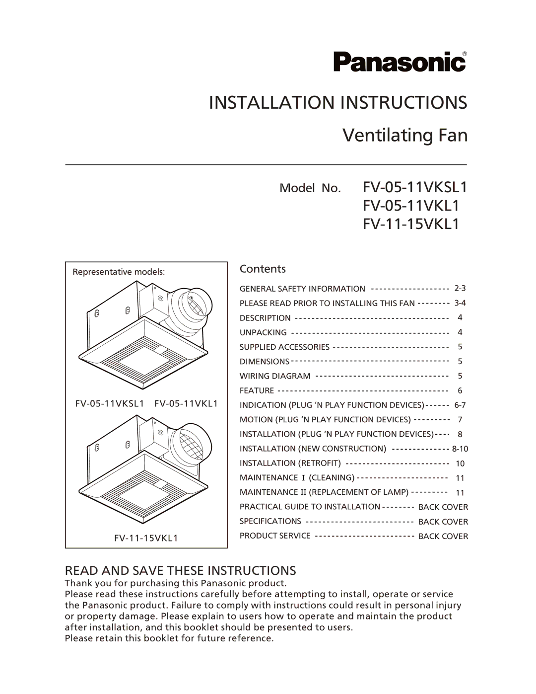
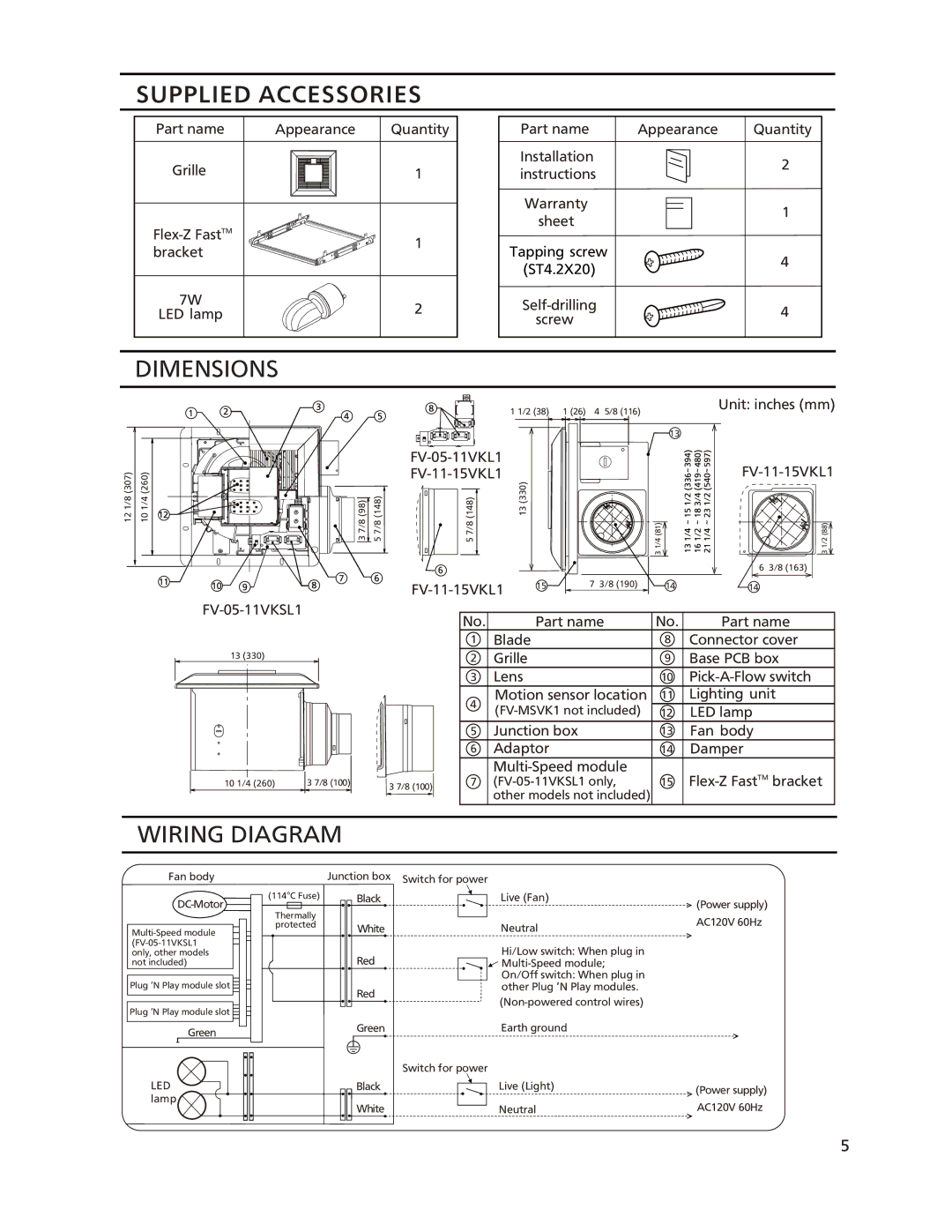
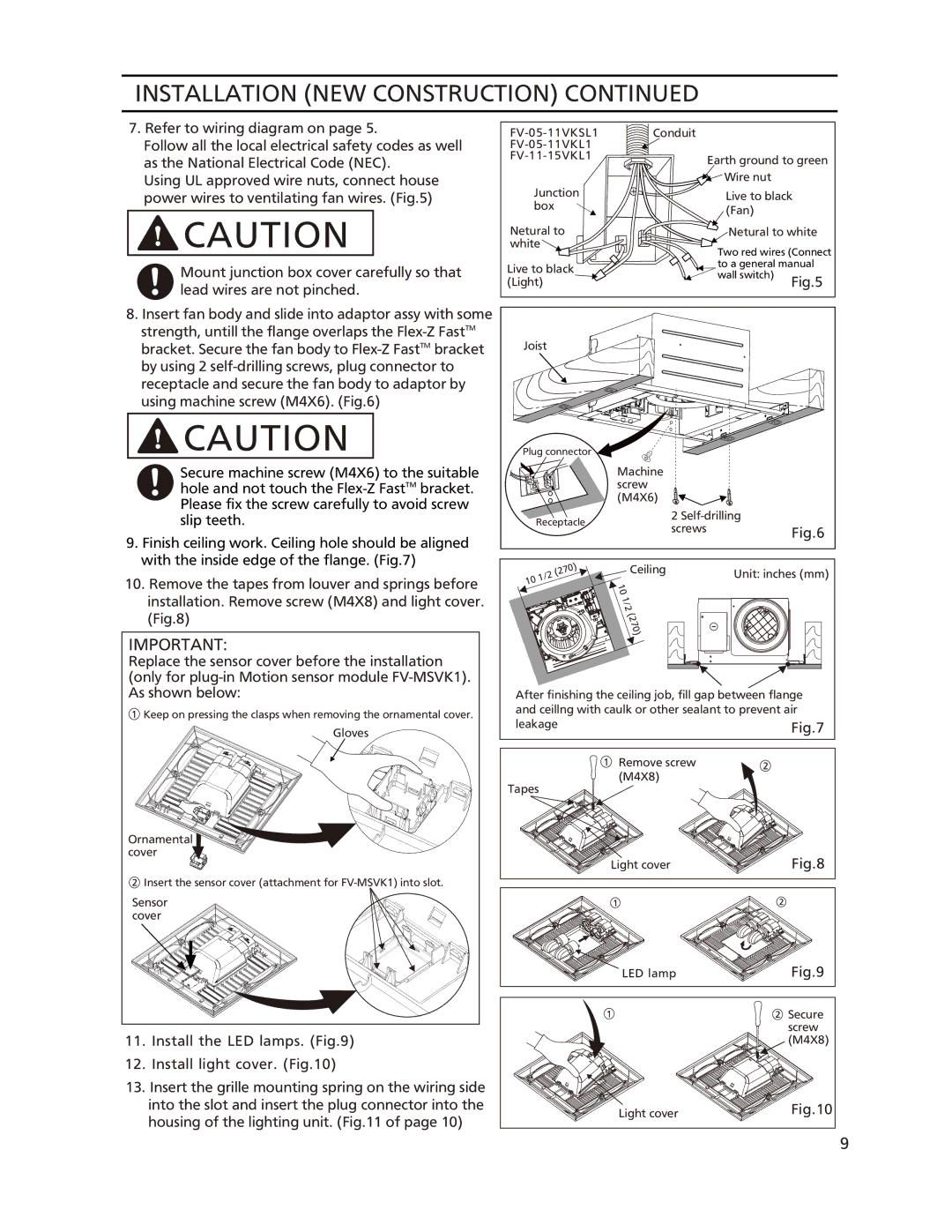
Before turn on the light, make sure the connector at the correct position. If not, the lighting can’t work.
The claw of connector must latch the rib completely.
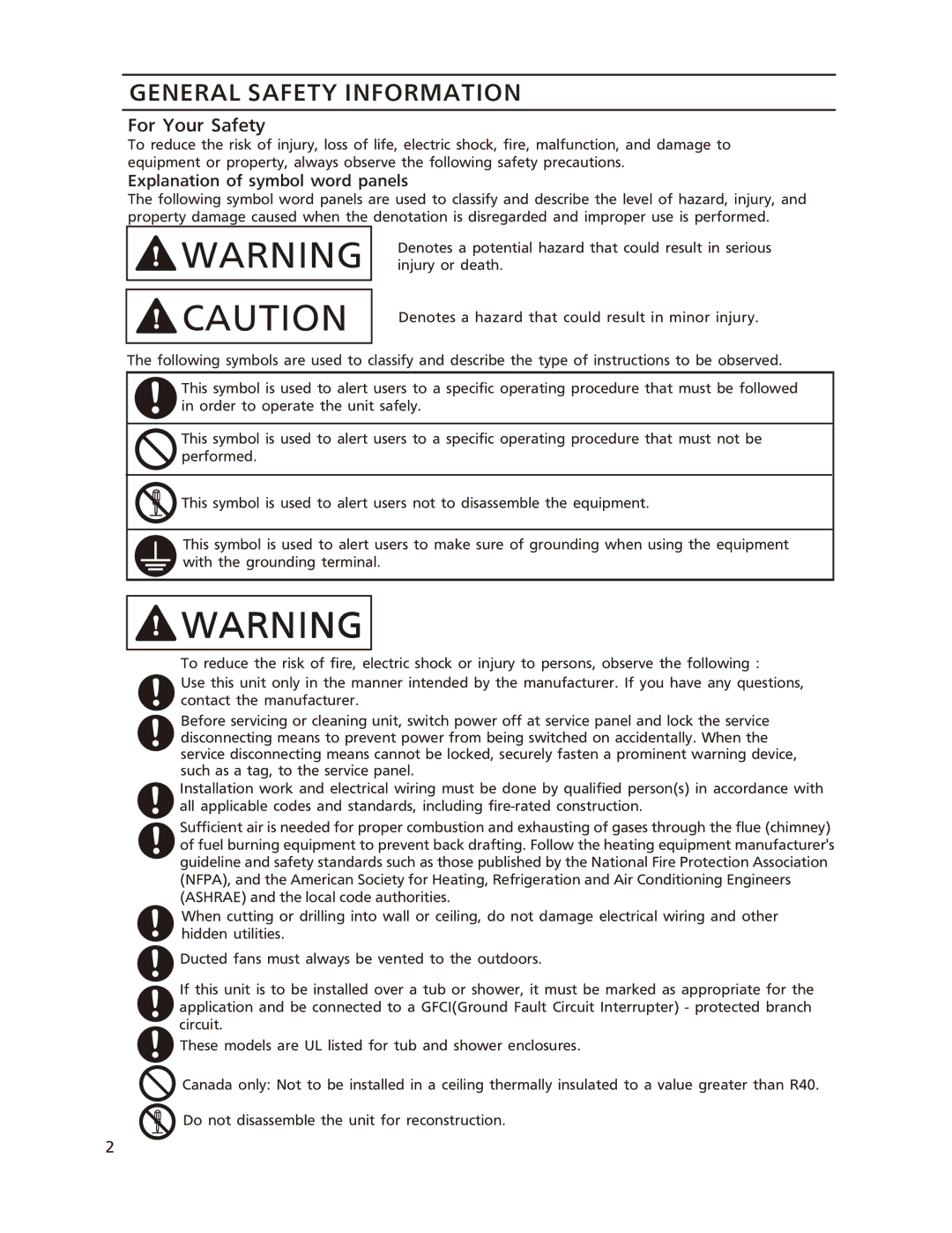
14.Plug in the specified devices as your choice (refer to installation on page 8). Insert the motion sensor
15.Adjust
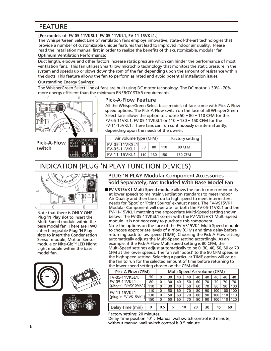
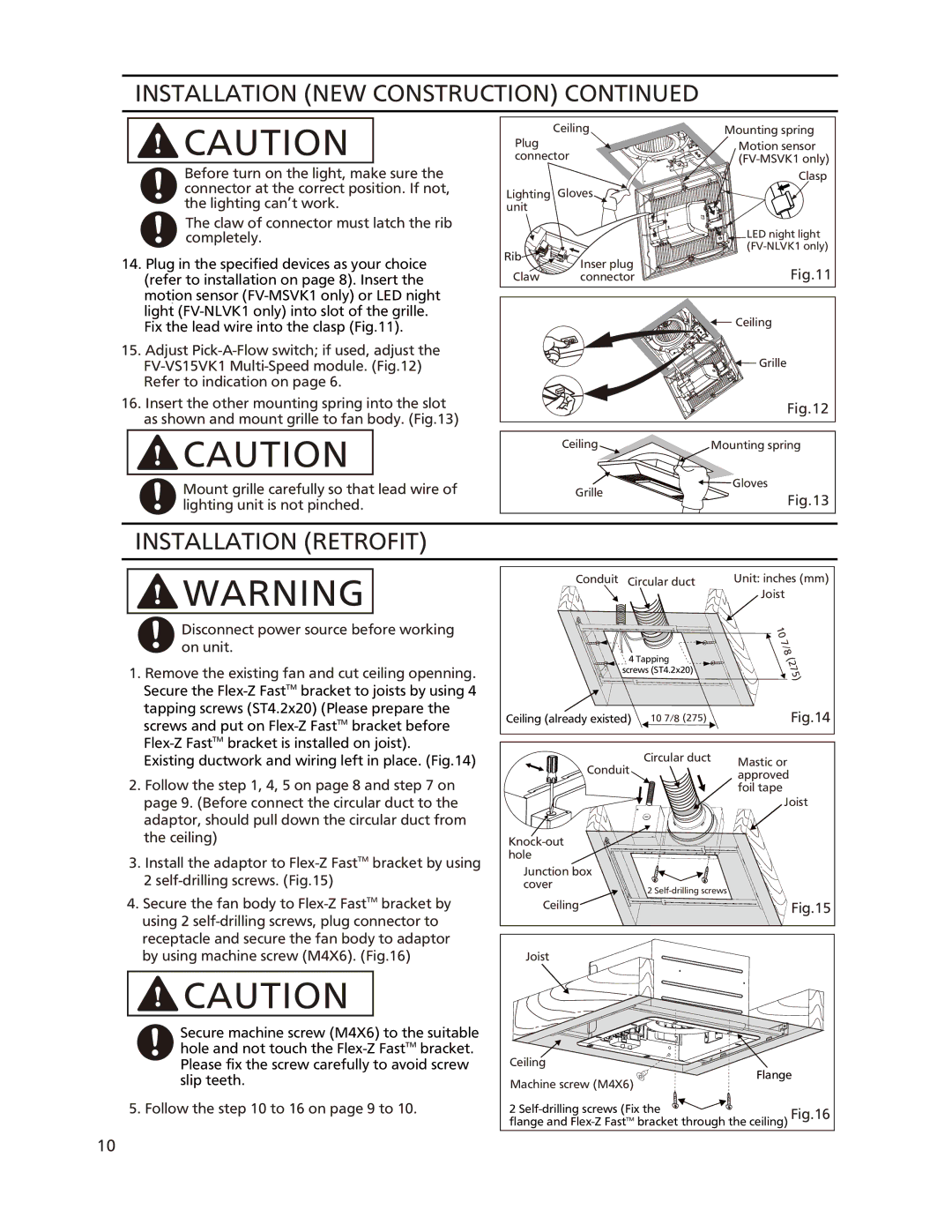
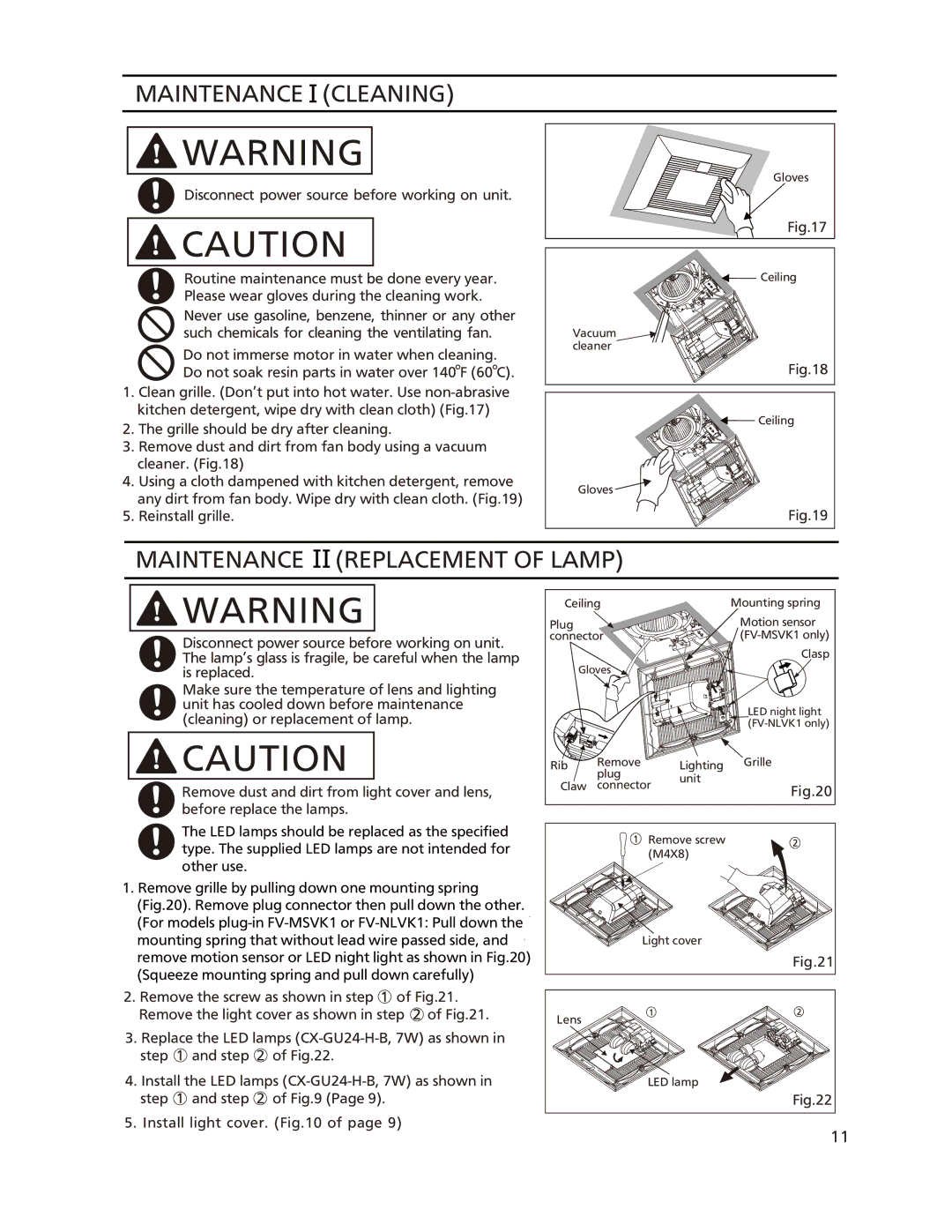
16.Insert the other mounting spring into the slot as shown and mount grille to fan body. (Fig.13)
![]()
![]() CAUTION
CAUTION
Mount grille carefully so that lead wire of lighting unit is not pinched.
Plug | Ceiling | Mounting spring |
| Motion sensor | |
connector | ||
|
| Clasp |
Lighting | Gloves |
|
unit |
|
|
|
| LED night light |
Rib |
| |
Inser plug |
| |
| Fig.11 | |
Claw | connector | |
![]() Ceiling
Ceiling
Grille |
Fig.12
Ceiling | Mounting spring |
![]() Gloves
Gloves
Grille
Fig.13
INSTALLATION (RETROFIT)
![]()
![]() WARNING
WARNING
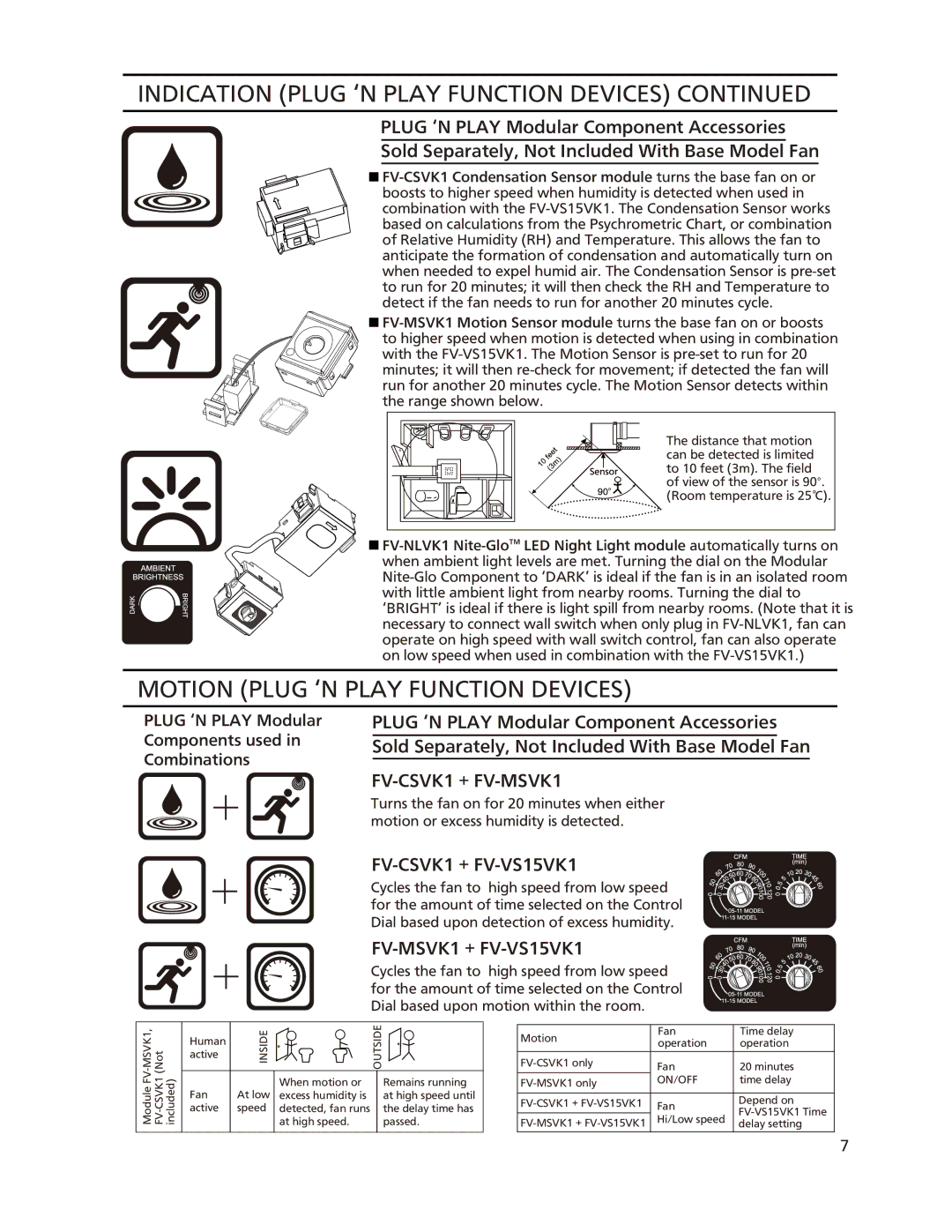
Disconnect power source before working on unit.
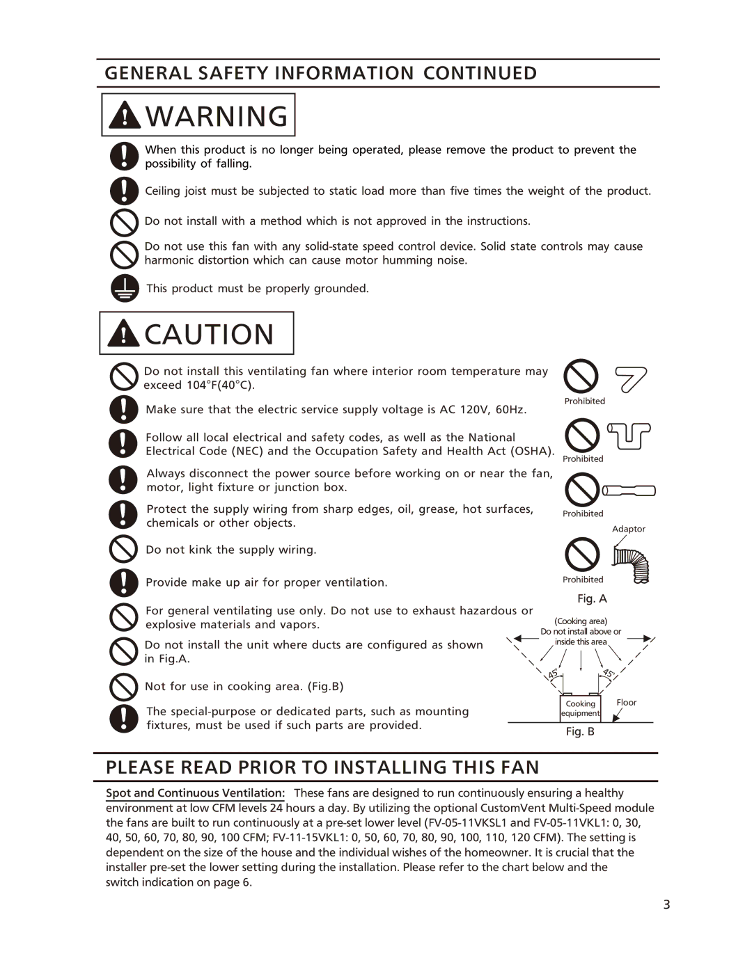
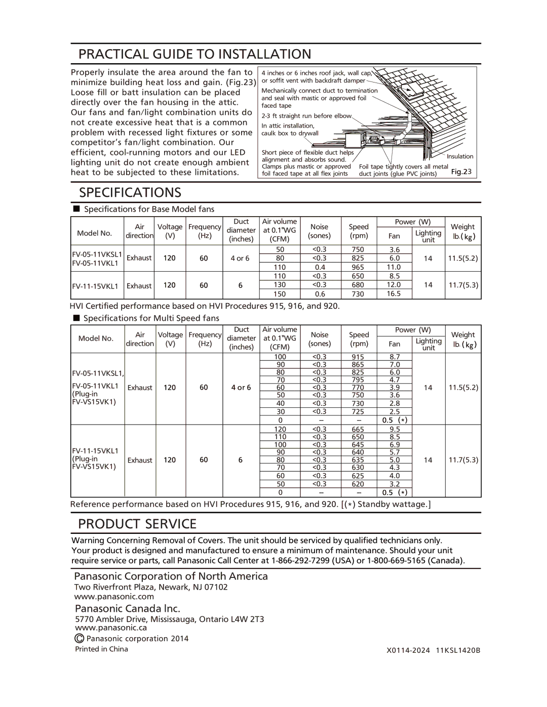
1.Remove the existing fan and cut ceiling openning. Secure the
Existing ductwork and wiring left in place. (Fig.14)
2.Follow the step 1, 4, 5 on page 8 and step 7 on page 9. (Before connect the circular duct to the adaptor, should pull down the circular duct from the ceiling)
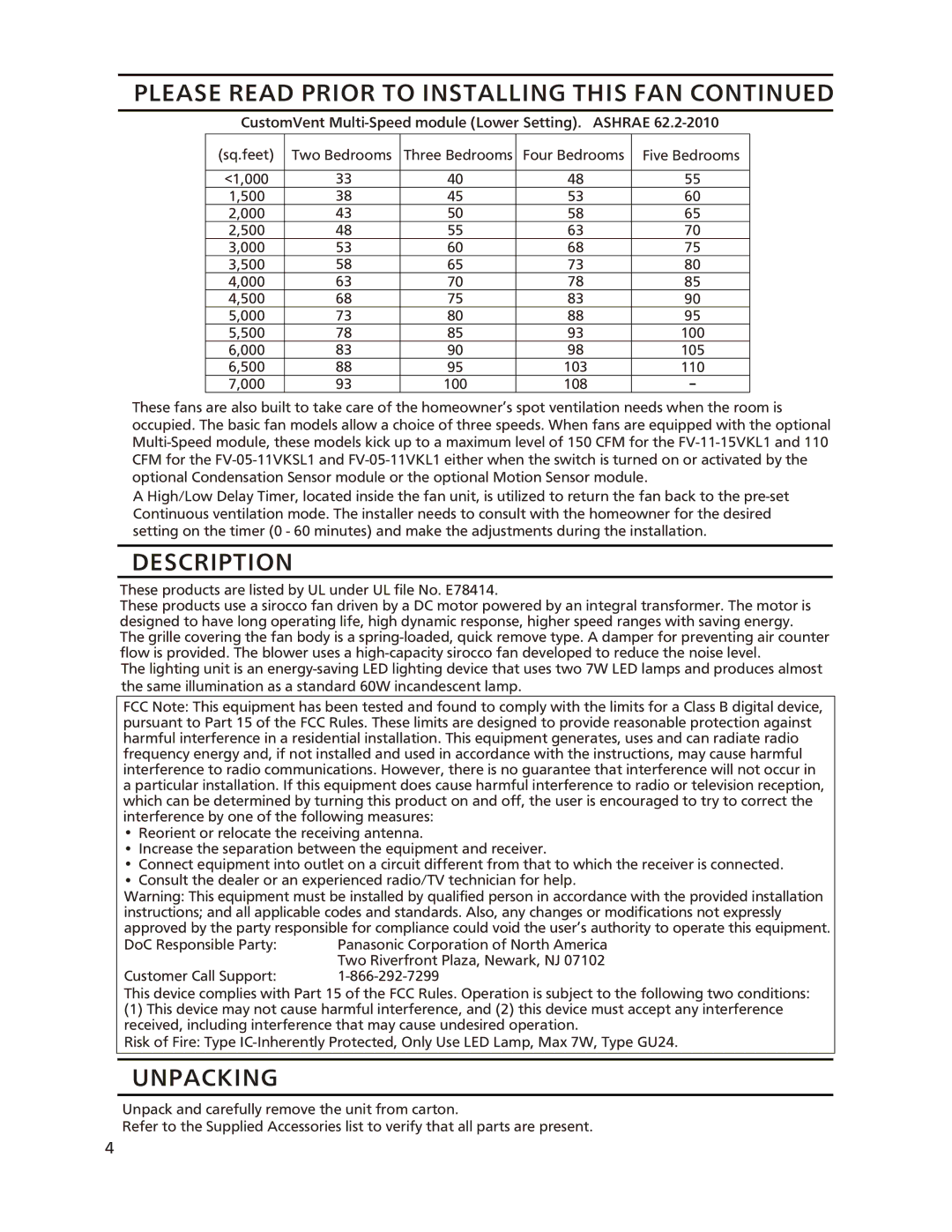
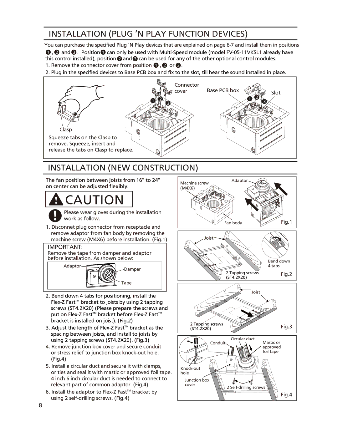
3.Install the adaptor to
4.Secure the fan body to
![]()
![]() CAUTION
CAUTION
Secure machine screw (M4X6) to the suitable hole and not touch the
5. Follow the step 10 to 16 on page 9 to 10.
Conduit Circular duct | Unit: inches (mm) |
| Joist |
|
| 10 | |
|
| 7/8 | |
4 Tapping | (275) | ||
screws (ST4.2x20) | |||
| |||
Ceiling (already existed) | 10 7/8 (275) | Fig.14 | |
Conduit | Circular duct | Mastic or |
| ||
| approved | |
|
| |
|
| foil tape |
|
| Joist |
|
| |
hole |
|
|
Junction box |
|
|
cover | 2 |
|
|
| |
Ceiling |
| Fig.15 |
Joist |
|
|
Ceiling
Flange
Machine screw (M4X6)
2 ![]()
![]()
![]() Fig.16 flange and
Fig.16 flange and
10