Motorola 6816101H01-A service manual Factory Reset, CPS Programming Setup

Page 45

Factory Reset

4-3

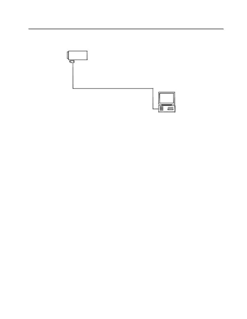
Refer to the diagram below for the programming setup.

Radio

Programming Cable

PMDN4043_R

Comm

Port

Figure 4-1 CPS Programming Setup

3.1To Read Radio Data to a PC

1.Turn off the radio.

2.Connect the programming cable to the radio.

3.Press and hold Programmable Button 1 (top side button on the radio), then turn on the radio.

4.The radio beeps once. Immediately release Programmable Button 1. The radio‟s LED illuminates in orange.

5.Click the Read button on the CPS.

6.The CPS shows a reading progress bar.

3.2To Write Data to a Radio

1.Turn off the radio.

2.Connect the programming cable to the radio

3.Press and hold Programmable Button 1 (top side button on radio) then turn on the radio.

4.The radio beeps once. Immediately release Programmable Button 1. The radio‟s LED illuminates in orange.

5.Click the Write button on the CPS.

6.The CPS shows writing progress bar.

4.0Factory Reset

This feature allows the user to restore the radio to the factory default settings.

1.Press and hold both the PTT and Programmable Button 2 (the lower programmable button), while turning on the radio.

2.The radio emits the Good Key Chirp tone upon completion of the factory reset.

Image 45
Contents Mag One by Motorola Radio Series Computer Software Copyrights Document History Page Federal Communication Commission FCC Regulations Safety InformationGuidelines Compliance with RF Exposure StandardsElectromagnetic Interference/Compatibility Hearing Aids Operational WarningsOther Medical Devices Use of communication devices while drivingOperational Cautions Intrinsically Safe Radio InformationOperational Cautions for Intrinsic Safe Equipment Repair Do Not Substitute Options or AccessoriesTable of Contents Glossary of Terms Radio ProgrammingWarranty Period and Return Instructions Warranty and Service SupportIntroduction Scope of ManualPiece Parts After Warranty PeriodTechnical Support Further Assistance From MotorolaUnit Level Radio Model InformationCPS Radio FeaturesPreventive Maintenance MaintenanceCleaning Procedures IntroductionSafe Handling of Cmos and Ldmos Devices Repair Procedures and Techniques General Disassembling and Reassembling the Radio General Radio Disassembly Detailed Radio Disassembly DetailedFront Cover from Chassis Disassembly Speaker Wire Radio Disassembly Detailed Radio Reassembly Detailed PC Board DisassemblyPC Board Reassembly Chassis and Front Cover Reassembly Radio Reassembly Detailed Speaker Connector Exploded View and Parts List Mechanical View and Parts ListReference Part Name QtyReference Part Name Qty Reference Part Name Qty PMUD2221A PMNN4071RCService Aids Motorola PartDescription Application Motorola Description Characteristics Application Test EquipmentProgramming Cable PMDN4043R Test Box PMDN4040R Cloning Cable PMDN4060R otesRadio Tuning Tuning Frequency Hardware Tuning Setup and ProcedureGround Contact Finger R425 R426 R216 FL701 R215 TP1 Subtone Level 42 ± 0.02kHz 96 ± 0.02kHz R425 R426 C722 Page Programming Your Radio Radio ProgrammingKit Number CPS ProgrammingCPS Programming Setup Factory ResetFactory Reset Accessories Audio Accessories Service KitsPublications VHF Band 1 Information 136-150 MHz A8 136-150 MHz VHF Model Chart and Test SpecificationModel Description LAH84JDC8AA4ANGeneral SpecificationsTransmitter ReceiverLAH84KDC8AA4AN VHF Band 2 Information 150 174 MHz A8 150-174 MHz VHFSpecifications LAH84QCC8AA4AN UHF Band 1 Information 403-425MHz A8 403-425 MHz UHFUHF UHF Band 2 Information 450 470MHz A8 450-470 MHz UHF Specifications UHF Band 4 Information 490 512 MHz A8 490-512 MHz UHF LAH84TCC8AA4ANPMAE4028A Specifications Glossary of Terms ResetTerm Definition PLLTPL ROMUHF VHF