Woodstock W1709 instruction manual Servicing Brake, Brake assembly Pads

Page 30

MAINTENANCE

Servicing Brake

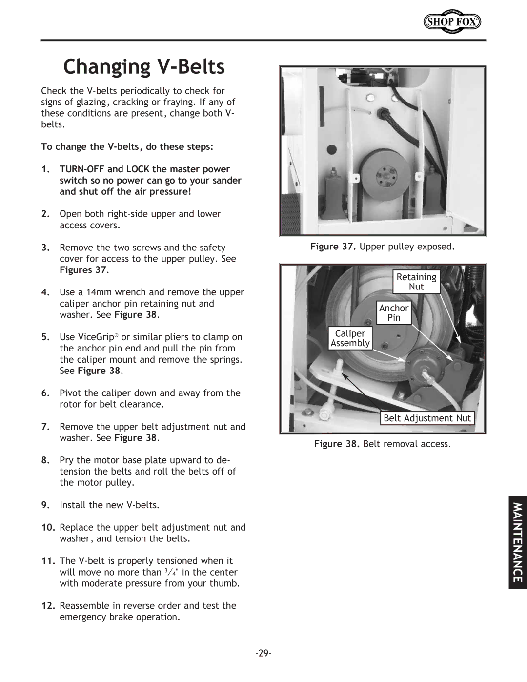
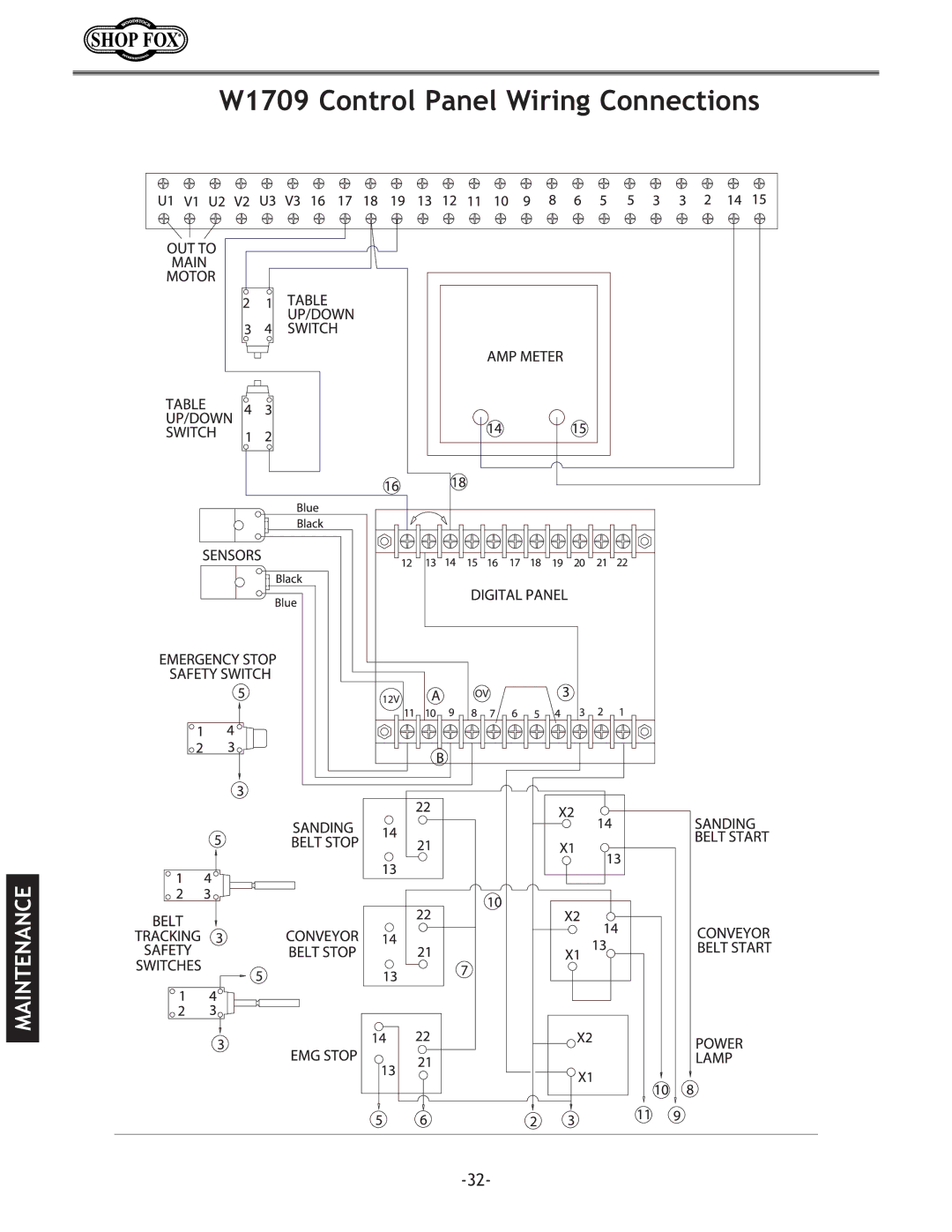
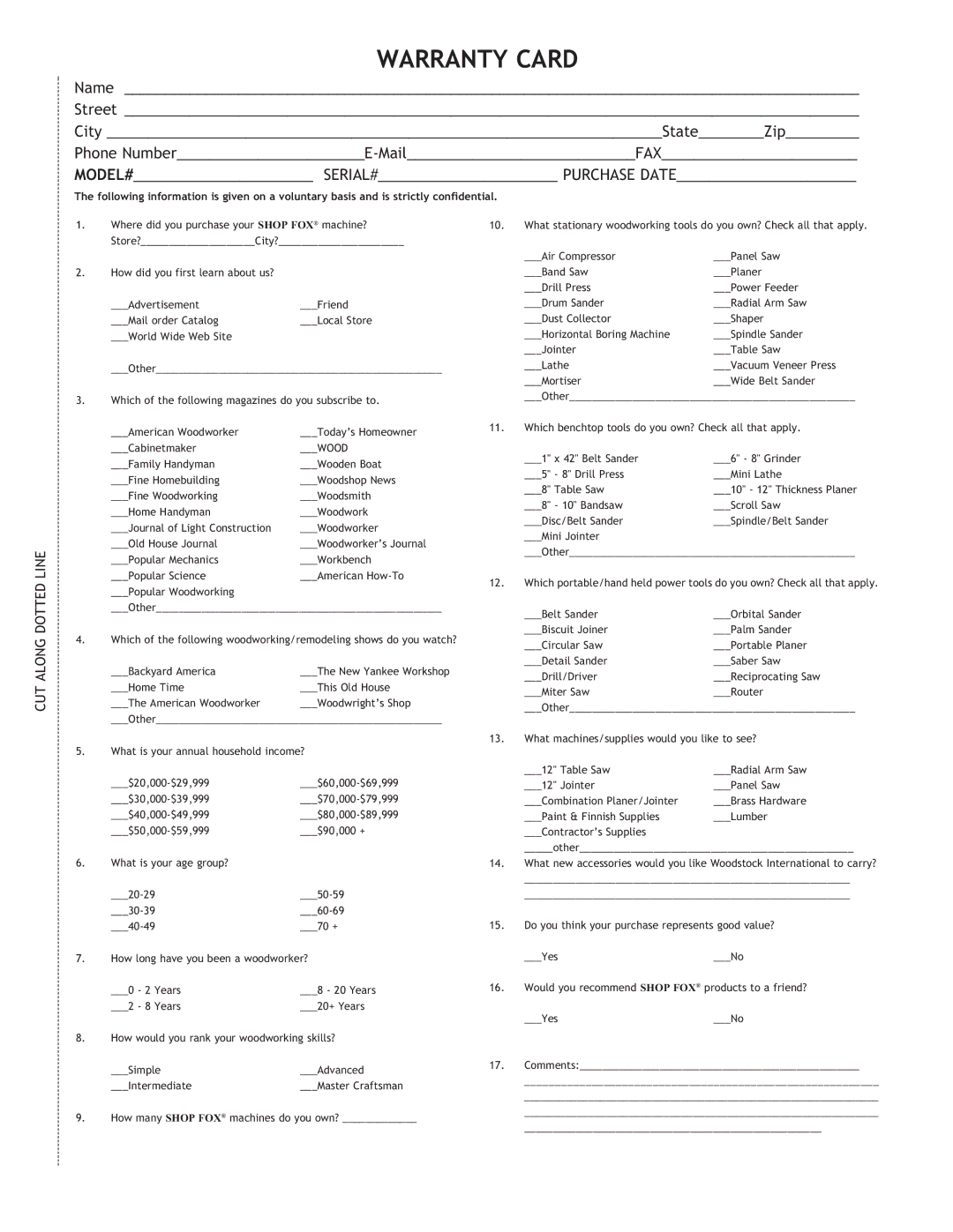
Any grease or oil on the emergency brake rotor creates the potential for reduced emergency braking ability. Check the brake rotor (shown in Figure 35) regularly to make sure it is clean. If it needs cleaning, only use automotive brake parts cleaner and a dry rag. DO NOT use water!

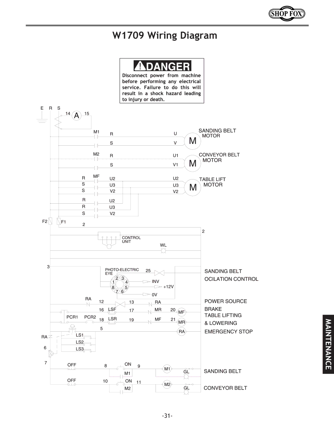
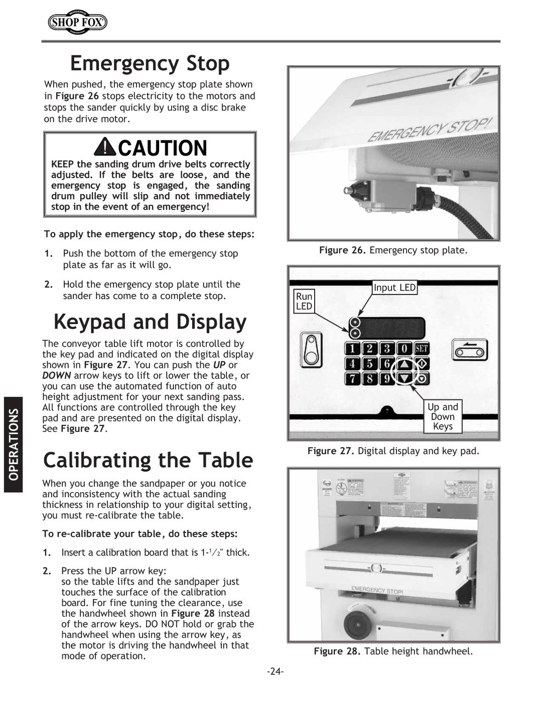
The brake pads shown in Figure 36 will eventually need to be replaced.

To check the condition of the brake pads, do these steps:

1.TURN-OFF and LOCK the master power switch so no power can go to your sander and shut off the air pressure!

2.Remove the lower right cover.

3.Measure the thickness of each pad. If a pad is below 18", then replace both.

To replace the brake pads, do these steps:

1.TURN-OFF and LOCK the master power switch so no power can go to your sander, and shut off the air pressure!

2.Use a 14mm wrench and remove the two caliper anchor pin retaining nuts and washer. See Figure 35.

3.Use ViceGrip® or similar pliers to clamp on the anchor pin end and pull the pin from the caliper mount and remove the springs. See Figure 35.

4.If the rotor is damaged, remove it and have it surfaced at a machine shop. Clean the rotor with automotive brake parts cleaner and handle it with a dry rag when installing.

5.To finish the job, install the new brake pads, reassemble and mount the caliper, and reconnect the air line if removed.

6.Test emergency brake operation!

Rotor

Retaining


Nut


Anchor


Pins


Caliper


Assembly

Figure 35. Brake assembly.

Brake
Pads

Figure 36. Brake caliper removed for access to

brake pads.

-28-

Image 30
Contents Wide Belt Sander Page Contents Woodstock Service and Support IntroductionAbout Your New Sander Warranty and Returns SpecificationsSafety First Standard Safety InstructionsDisconnect machine when cleaning, adjusting or servicing Keep stable footing and balance at all times Additional Safety Instructions for Sanders Avoiding Potential Injuries Correct body and hand positioningExtension Cords Electrical Requirements220V Operation GroundingAssembly Box ContentsUnpacking Cleaning Machine Shop PreparationAir Hose Installation Sanding Belt InstallationDust Collection Dust collection adaptersAdjustments General InformationPhoto-Electric Eye Belt tracking adjustment location Belt TrackingBelt oscillation adjustment Belt Oscillation SpeedBelt Tracking Safety Switch To adjust the belt tracking safety switches, do these stepsTo adjust the pressure rollers, do these steps Pressure RollersBelt Tension To tension the V-belts, do these stepsTo adjust the feed belt tension and tracking, do these steps Feed Belt Tension TrackingTable Stop Switches To adjust table stop switches, do these stepsDown Key Operations Control PanelTest Run Selecting SandpaperTo complete the test run, do these steps Setting Feed Speed Using the Load MeterTo change the feed belt speed do these steps Calibrating the Table Emergency StopKeypad and Display To apply the emergency stop, do these stepsBasic Sanding Quick TipTo sand a workpiece, do these steps Maintenance GeneralLubrication Cleaning Belts Servicing SeparatorsBrake assembly Pads Servicing BrakeChanging V-Belts FiguresTroubleshooting Symptom Possible Cause HOW to RemedyW1709 Wiring Diagram W1709 Control Panel Wiring Connections W1709 Switch Box Wiring Connections Parts Tool BOX Parts Elevation Screw Parts Conveyor Table Parts Piston Roller Shaft Parts Parts Parts Electrical Control BOX Accessories D3003 15 x 20 Cleaning Pad for Wide-Belt SandersWarranty Card BOX BELLINGHAM, WA