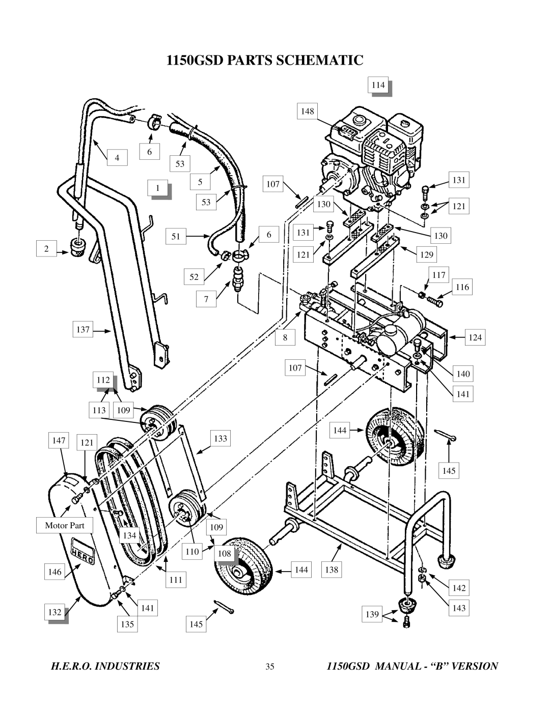
I.C.T.C. Holdings Corporation 1150GSD operating instructions Special Notes

Page 25

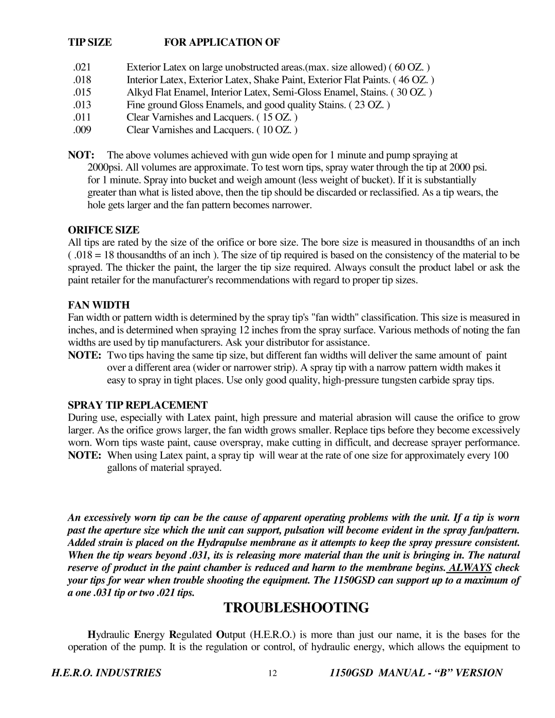
(REF# 90)

SPECIAL NOTES

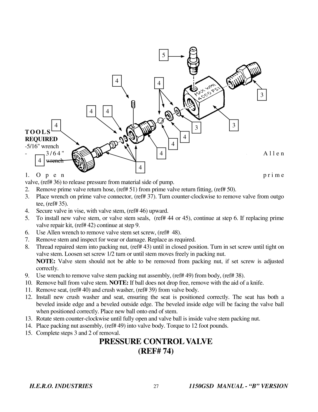
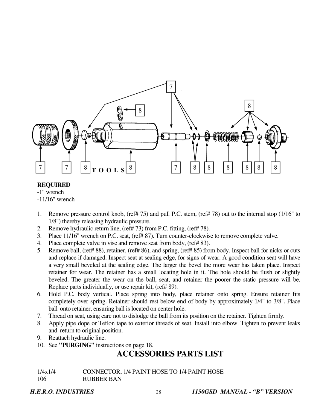
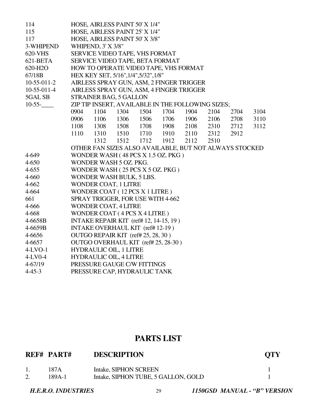
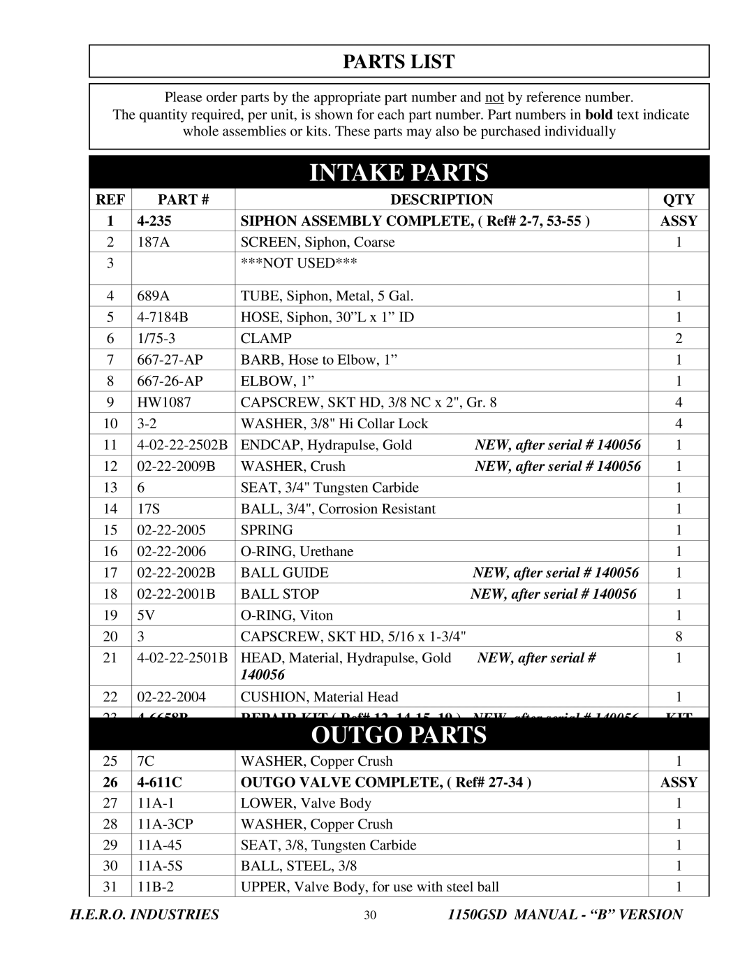
TOOLS REQUIRED -1/2" wrench -11/16" wrench -circlip pliers -torque wrench -grease

-vise grips

All gas driven units must remain level at all times. Tipping of the units will cause the oil from the engine crankcase to flow into the engine air cleaner, carburetor and cylinder head. This will cause starting and running difficulties. Keep unit level during service.

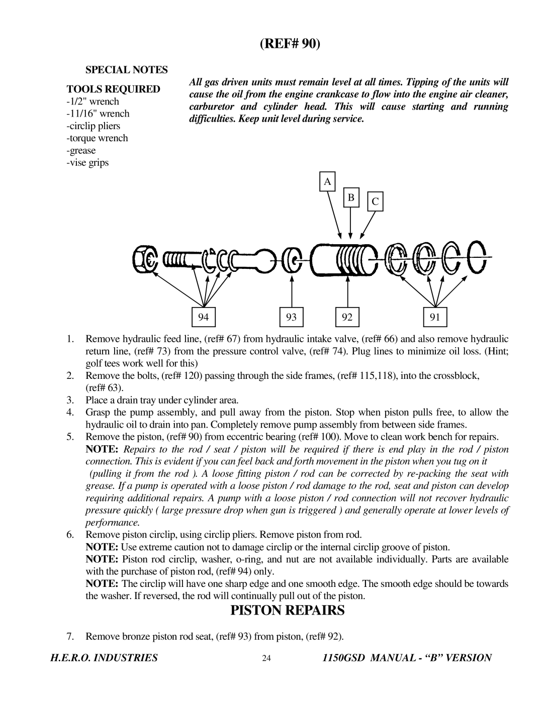
A

B

C


94

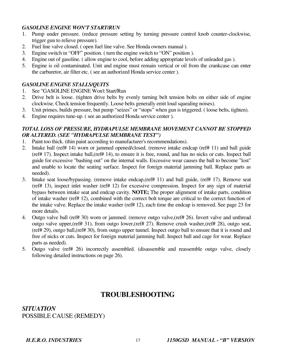
93

92

91

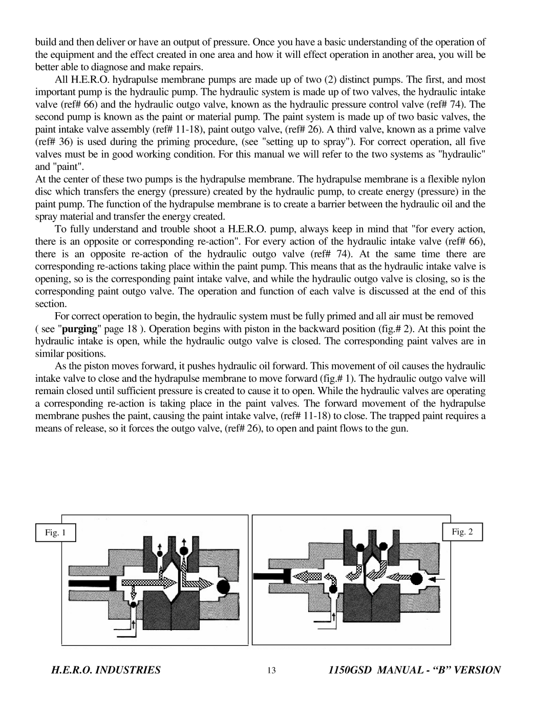
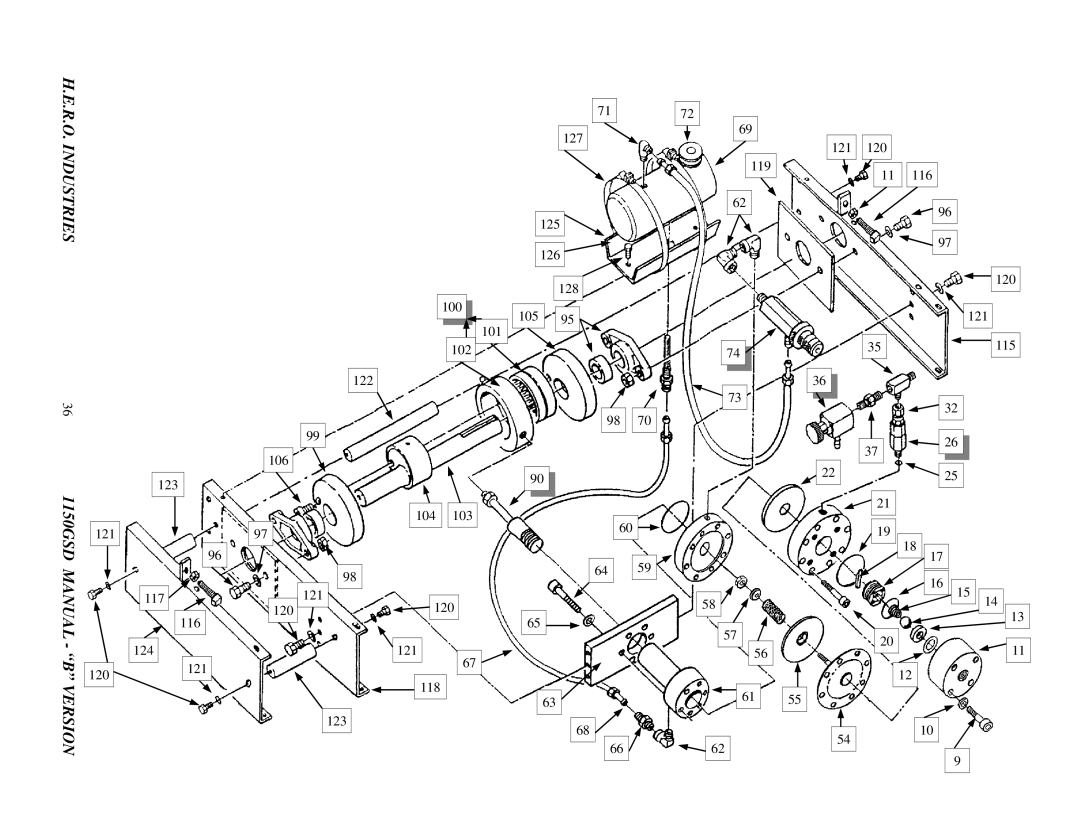
1.Remove hydraulic feed line, (ref# 67) from hydraulic intake valve, (ref# 66) and also remove hydraulic return line, (ref# 73) from the pressure control valve, (ref# 74). Plug lines to minimize oil loss. (Hint; golf tees work well for this)

2.Remove the bolts, (ref# 120) passing through the side frames, (ref# 115,118), into the crossblock, (ref# 63).

3.Place a drain tray under cylinder area.

4.Grasp the pump assembly, and pull away from the piston. Stop when piston pulls free, to allow the hydraulic oil to drain into pan. Completely remove pump assembly from between side frames.

5.Remove the piston, (ref# 90) from eccentric bearing (ref# 100). Move to clean work bench for repairs. NOTE: Repairs to the rod / seat / piston will be required if there is end play in the rod / piston connection. This is evident if you can feel back and forth movement in the piston when you tug on it (pulling it from the rod ). A loose fitting piston / rod can be corrected by re-packing the seat with grease. If a pump is operated with a loose piston / rod damage to the rod, seat and piston can develop requiring additional repairs. A pump with a loose piston / rod connection will not recover hydraulic pressure quickly ( large pressure drop when gun is triggered ) and generally operate at lower levels of performance.

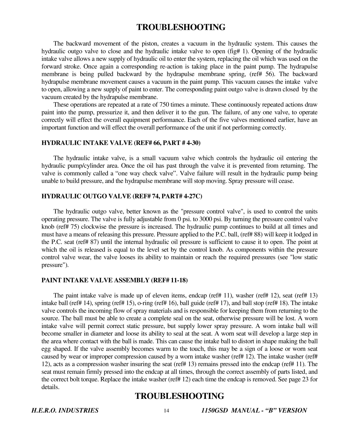
6.Remove piston circlip, using circlip pliers. Remove piston from rod.

NOTE: Use extreme caution not to damage circlip or the internal circlip groove of piston.

NOTE: Piston rod circlip, washer, o-ring, and nut are not available individually. Parts are available with the purchase of piston rod, (ref# 94) only.

NOTE: The circlip will have one sharp edge and one smooth edge. The smooth edge should be towards the washer. If reversed, the rod will continually pull out of the piston.

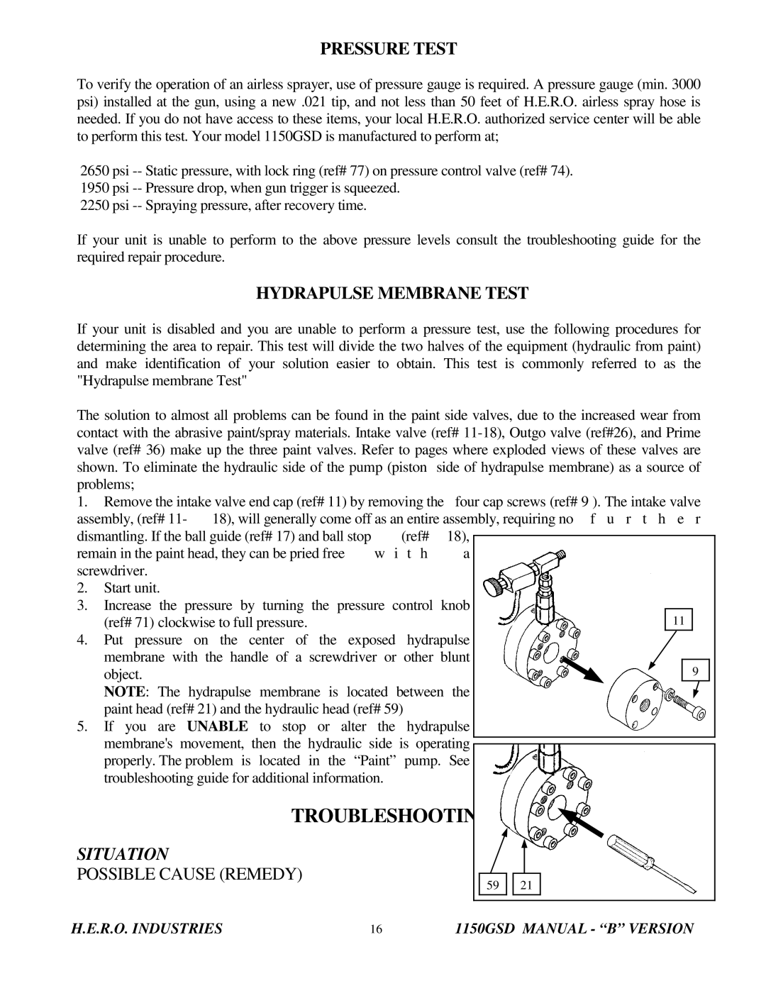
PISTON REPAIRS

7.Remove bronze piston rod seat, (ref# 93) from piston, (ref# 92).

H.E.R.O. INDUSTRIES

24

1150GSD MANUAL - “B” VERSION

Image 25
Contents Version Beginning AT Serial Number Airless Spray EquipmentR.O. Warranty Table of Contents Important Safety PrecautionsAlways Always R.O. Airless Spray PaintingInstructions Setting UP to SprayHydrapulse B Version Beginning AT Serial Number E R a T I N GAlways Paint Straining Special Notes and Instructions Flushing the Unit AT Shutdown Or Color ChangeAirless Spray Painting GAS EngineAirless Spray Painting Suggestions and Technique Suggestions and TechniqueSpray TIP Selection Spray TIP Replacement TroubleshootingTIP Size For Application Orifice SizeR.O. Industries 1150GSD Manual B Version Hydraulic Intake Valve REF# 66 Paint Intake Valve Assembly REF#Hydraulic Outgo Valve REF# 74, PART# 4-27C Prime Valve REF# 36, PART# Paint Outgo Valve REF# 26, PART# 4-611CSituation Gasoline Engine Wont START/RUN No PRESSURE, Blue Hydraulic Fluid in Paint Troubleshooting Sprayer does not Prime with Paint Spray Pattern is Spotty or Uneven Hydrapulse Membrane ReplacementRemoval Replacement of Intake SeatTools Required Piston RepairsSpecial Notes Outgo Valve REF# Prime Valve Repairs O L S Required Pressure Control ValveO L S Accessories Parts ListZIP TIP INSERT, Available in the Following Sizes Parts ListAssy Description QTYKIT Outgo Parts Industries 1150GSD Manual B Version Drive Parts Decals 1150GSD Parts Schematic Manual B Version