Repair | P 10 / 22 |
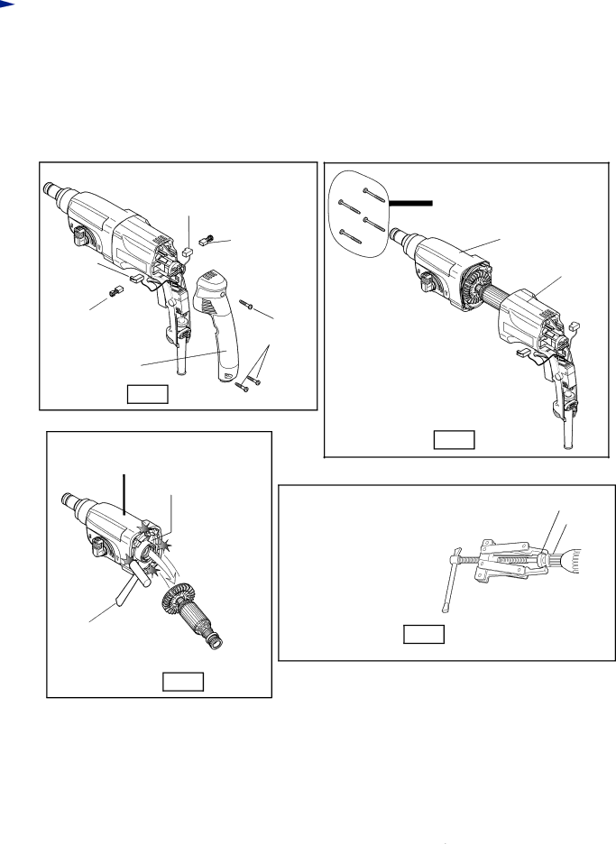
<9 > Disassembling armature
1.Remove handle cover by unscrewing 3 pcs. of tapping screw 4 x 45. And remove carbon brushes as illustrated in Fig. 40.
2.Separate gear housing together with armature, from motor housing by unscrewing 4 pcs. of tapping screw 4 x 45 as illustrated in Fig. 41.
3.Slightly hitting the edge of gear housing with plastic hammer, remove armature from inner housing assembled in gear housing. See Fig. 42.
4.Ball bearings of fan side and commutator side can be removed with No.1R269 "Bearing extractor (small)". See Fig. 43.
|
| Tapping s |
Brush holder |
| crew 4 x 45 : 4 pcs. |
| Carbon brush | Gear housing |
Brush |
| Motor housing |
holder |
| |
|
| |
Carbon brush | Tapping screw |
|
|
| |
Handle | 4 x 25 : 3 pcs. |
|
|
| |
cover |
|
|
Fig. 40 |
|
|
|
| Fig. 41 |
Gear housing |
|
|
Inner housing |
|
|
|
| Ball bearing |
|
| Armature |
No.1R269![]() "Bearing extractor (small)"
"Bearing extractor (small)"
Plastic hammer
Fig. 43
Fig. 42