Miller Electric 333, 271, 383, 293, 273 Threading Welding Wire and Adjusting Pressure Roll Tension

Page 18

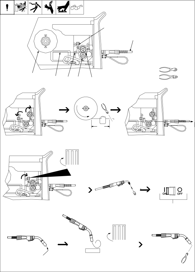
3-11. Threading Welding Wire and Adjusting Pressure Roll Tension


1

Wire Spool


2

Welding Wire


3

Inlet Wire Guide


4

Pressure Adjustment Knob


5

Drive Roll

4


6

Outlet Wire Guide


7

Gun Conduit Cable


7

Lay gun cable out straight.


Tools Needed:

1

2

3

5

6


Open pressure assembly.

Tighten

.Hold wire tightly to keep it from unraveling.

150 mm

(6 in)

Pull and hold wire; cut off end.

Push wire thru guides into gun;


continue to hold wire.

.Use pressure indicator

scale to set a desired drive roll pressure.


1


Pressure


2


Indicator


3


Scale


4


Close and tighten pressure assembly, and let go of wire.

Press gun trigger until wire comes out of gun. Reinstall contact tip and nozzle

Remove gun nozzle and contact tip.

Turn On.

Tighten


1


2


WOOD


3


4


Feed wire to check drive roll pressure.


Cut off wire. Close

Tighten knob enough to prevent slipping.


and latch door.

Ref. 802 064-D / S-0627-A

OM-223 194 Page 14

Image 18
Contents OM-223 194E 2006−09 ProcessesDescription From Miller to You Table of Contents Directives StandardsDecstatMilan6/05 Electric Shock can kill Symbol UsageArc Welding Hazards Fumes and Gases can be hazardousFlying Metal can injure eyes ARC Rays can burn eyes and skinWelding can cause fire or explosion Buildup of GAS can injure or killCalifornia Proposition 65 Warnings Principal Safety Standards EMF Information− Definitions Electric shock can killDo not move or operate unit Where it could tipFalling unit can cause injury Cylinders can expolde ifCan kill Electrical shock from wiringWear approved safety Working on this machine− Installation SpecificationsDuty Cycle And Overheating Volt-Ampere CurvesModel Installing Gas Supply Installing Wire Spool and Adjusting Hub Tension271 273 293 333 383 Positoning Jumper Links 230/400V 3-Phase ModelsElectrical Service Guide 230 400L2 L3 Installing Drive Rolls and Wire Guide Aligning Drive Rolls and Wire GuideThreading Welding Wire and Adjusting Pressure Roll Tension Using Gun/Cable Holder Setting Gun Polarity for Wire Type Optional− Operation Controls for Migmatic 271/273Controls for Migmatic 293/333 Controls for Migmatic Run-In, Burnback Optional and Spot Weld Timer ControlsSpot Weld Timer Run-In ControlCircuit Breaker CB1 − Maintenance &TROUBLESHOOTINGRoutine Maintenance Unit OverloadReplace Z1 if necessary TroubleshootingCheck voltage switchs. Replace if necessary Nections. Check secondary voltages. Replace T1 if necessaryOM-223 194 − Electrical Diagrams Circuit Diagram for MigmaticCircuit Diagram for Migmatic 273 400 VAC Circuit Diagram for Migmatic 293 400 VAC Circuit Diagram for Migmatic 333 400 VAC Circuit Diagram for Migmatic 383 400 VAC − Parts List Wrapper Assembly, All ModelsPart Description Quantity Main Assembly for Migmatic Dia Part Description Quantity Mkgs Main Assembly for Migmatic Dia Part Description Main Assembly for Migmatic PL2 Main Assembly for Migmatic PL1 Main Assembly for Migmatic TP1 See Table Drive Roll & Wire Guide Kits Wire Drive and Gears 2 rollWire Drive and Gears 4 roll 1.0 mm Drive Roll And Wire Guide Kits 2 Roll ModelsDrive Roll And Wire Guide Kits 4 Roll Models 1.2 mmPage Page Effective January 1 For assistance in filing or settling claims, contact Your distributor and/or equipment manufacturer’sTransportation Department