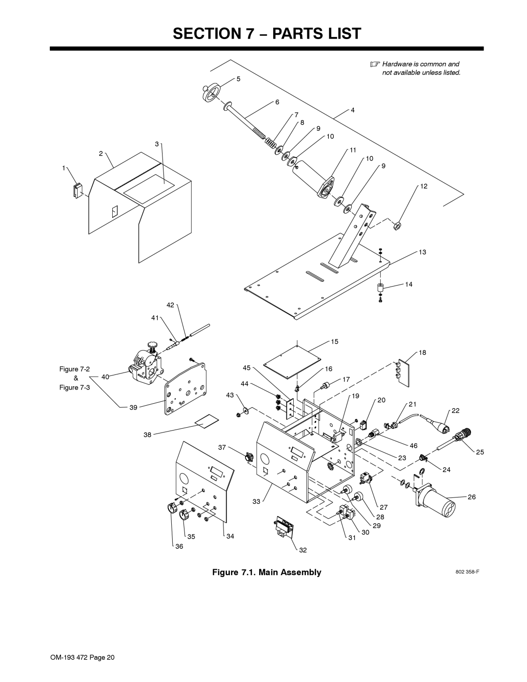
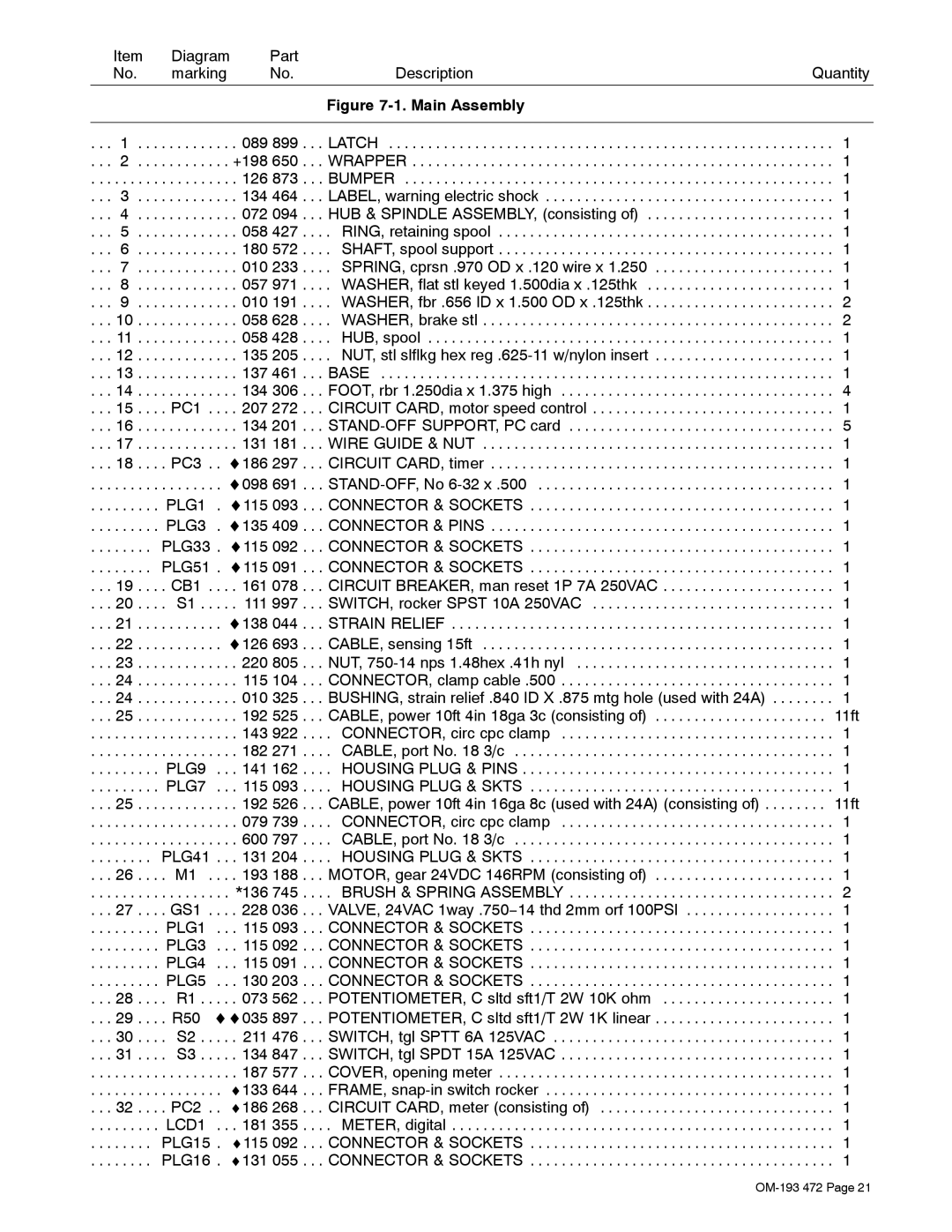
| Item | Diagram | Part |
|
| |
| No. | marking | No. | Description | Quantity | |
|
|
|
|
|
|
|
|
|
|
|
| Figure |
|
|
|
|
|
|
|
|
. . . | 1 . . . | . . . . . . . | . . | . 089 899 . . . | LATCH | . . . 1 |
. . . 2 . . . | . . . . . . . | . . | +198 650 . . . | WRAPPER | . . . 1 | |
. . . | . . . . . . | . . . . . . . | . . | . 126 873 . . . | BUMPER | . . . 1 |
. . . | 3 . . . | . . . . . . . | . . | . 134 464 . . . | LABEL, warning electric shock | . . . 1 |
. . . | 4 . . . | . . . . . . . | . . | . 072 094 . . . | HUB & SPINDLE ASSEMBLY, (consisting of) | . . . 1 |
. . . | 5 . . . | . . . . . . . | . . | . 058 427 . . . | . RING, retaining spool | . . . 1 |
. . . | 6 . . . | . . . . . . . | . . | . 180 572 . . . | . SHAFT, spool support | . . . 1 |
. . . | 7 . . . | . . . . . . . | . . | . 010 233 . . . | . SPRING, cprsn .970 OD x .120 wire x 1.250 | . . . 1 |
. . . | 8 . . . | . . . . . . . | . . | . 057 971 . . . | . WASHER, flat stl keyed 1.500dia x .125thk | . . . 1 |
. . . | 9 . . . | . . . . . . . | . . | . 010 191 . . . | . WASHER, fbr .656 ID x 1.500 OD x .125thk | . . . 2 |
. . . 10 . . . | . . . . . . . | . . | . 058 628 . . . | . WASHER, brake stl | . . . 2 | |
. . . 11 . . . | . . . . . . . | . . | . 058 428 . . . | . HUB, spool | . . . 1 | |
. . . 12 . . . | . . . . . . . | . . | . 135 205 . . . | . NUT, stl slflkg hex | . . . 1 | |
. . . 13 . . . | . . . . . . . | . . | . 137 461 . . . | BASE | . . . 1 | |
. . . 14 . . . | . . . . . . . | . . | . 134 306 . . . | FOOT, rbr 1.250dia x 1.375 high | . . . 4 | |
. . . 15 . . . | . PC1 . | . . | . 207 272 . . . | CIRCUIT CARD, motor speed control | . . . 1 | |
. . . 16 . . . | . . . . . . . | . . | . 134 201 . . . | . . . 5 | ||
. . . 17 . . . | . . . . . . . | . . | . 131 181 . . . | WIRE GUIDE & NUT | . . . 1 | |
. . . 18 . . . | . PC3 . | . ♦186 297 . . . | CIRCUIT CARD, timer | . . . 1 | ||
. . . | . . . . . . | . . . . . . . | . ♦098 691 . . . | . . . 1 | ||
. . . | . . . . . . | PLG1 . ♦115 093 . . . | CONNECTOR & SOCKETS | . . . 1 | ||
. . . | . . . . . . | PLG3 | . ♦135 409 . . . | CONNECTOR & PINS | . . . 1 | |
. . . | . . . . . | PLG33 . ♦115 092 . . . | CONNECTOR & SOCKETS | . . . 1 | ||
. . . | . . . . . | PLG51 . ♦115 091 . . . | CONNECTOR & SOCKETS | . . . 1 | ||
. . . 19 . . . | . CB1 . | . . | . 161 078 . . . | CIRCUIT BREAKER, man reset 1P 7A 250VAC | . . . 1 | |
. . . 20 . . . | . S1 . . | . . | . 111 997 . . . | SWITCH, rocker SPST 10A 250VAC | . . . 1 | |
. . . 21 . . . | . . . . . . . | . ♦138 044 . . . | STRAIN RELIEF | . . . 1 | ||
. . . 22 . . . | . . . . . . . | . ♦126 693 . . . | CABLE, sensing 15ft | . . . 1 | ||
. . . 23 . . . | . . . . . . . | . . | . 220 805 . . . | NUT, | . . . 1 | |
. . . 24 . . . | . . . . . . . | . . | . 115 104 . . . | CONNECTOR, clamp cable .500 | . . . 1 | |
. . . 24 . . . | . . . . . . . | . . | . 010 325 . . . | BUSHING, strain relief .840 ID X .875 mtg hole (used with 24A) | . . . 1 | |
. . . 25 . . . | . . . . . . . | . . | . 192 525 . . . | CABLE, power 10ft 4in 18ga 3c (consisting of) | . . 11ft | |
. . . | . . . . . . | . . . . . . . | . . | . 143 922 . . . | . CONNECTOR, circ cpc clamp | . . . 1 |
. . . | . . . . . . | . . . . . . . | . . | . 182 271 . . . | . CABLE, port No. 18 3/c | . . . 1 |
. . . | . . . . . . | PLG9 | . . . 141 162 . . . | . HOUSING PLUG & PINS | . . . 1 | |
. . . | . . . . . . | PLG7 | . . . 115 093 . . . | . HOUSING PLUG & SKTS | . . . 1 | |
. . . 25 . . . | . . . . . . . | . . | . 192 526 . . . | CABLE, power 10ft 4in 16ga 8c (used with 24A) (consisting of) | . . 11ft | |
. . . | . . . . . . | . . . . . . . | . . | . 079 739 . . . | . CONNECTOR, circ cpc clamp | . . . 1 |
. . . | . . . . . . | . . . . . . . | . . | . 600 797 . . . | . CABLE, port No. 18 3/c | . . . 1 |
. . . | . . . . . | PLG41 | . . | . 131 204 . . . | . HOUSING PLUG & SKTS | . . . 1 |
. . . 26 . . . | . M1 . . . . 193 188 . . . | MOTOR, gear 24VDC 146RPM (consisting of) | . . . 1 | |||
. . . | . . . . . . | . . . . . . . | . . | *136 745 . . . | . BRUSH & SPRING ASSEMBLY | . . . 2 |
. . . 27 . . . | . GS1 . | . . | . 228 036 . . . | VALVE, 24VAC 1way .750−14 thd 2mm orf 100PSI | . . . 1 | |
. . . | . . . . . . | PLG1 | . . . 115 093 . . . | CONNECTOR & SOCKETS | . . . 1 | |
. . . | . . . . . . | PLG3 | . . . 115 092 . . . | CONNECTOR & SOCKETS | . . . 1 | |
. . . | . . . . . . | PLG4 | . . . 115 091 . . . | CONNECTOR & SOCKETS | . . . 1 | |
. . . | . . . . . . | PLG5 | . . . 130 203 . . . | CONNECTOR & SOCKETS | . . . 1 | |
. . . 28 . . . | . R1 . . | . . | . 073 562 . . . | POTENTIOMETER, C sltd sft1/T 2W 10K ohm | . . . 1 | |
. . . 29 . . . . R50 ♦♦035 897 . . . POTENTIOMETER, C sltd sft1/T 2W 1K linear . . . . . . . . . . . . . . . . . . . . . . . 1
. . . 30 . . . . S2 . . . . . 211 476 . . . SWITCH, tgl SPTT 6A 125VAC . . . . . . . . . . . . . . . . . . . . . . . . . . . . . . . . . . . . 1
. . . 31 . . . . S3 . . . . . 134 847 . . . SWITCH, tgl SPDT 15A 125VAC . . . . . . . . . . . . . . . . . . . . . . . . . . . . . . . . . . . 1
. . . . . . . . . . . . . . . . . . . 187 577 . . . COVER, opening meter . . . . . . . . . . . . . . . . . . . . . . . . . . . . . . . . . . . . . . . . . . . 1
. . . . . . . . . . . . . . . . . ♦133 644 . . . FRAME,
. . . 32 . . . . PC2 . . ♦186 268 . . . CIRCUIT CARD, meter (consisting of) . . . . . . . . . . . . . . . . . . . . . . . . . . . . . . 1
. . . . . . . . . LCD1 . . . 181 355 . . . . METER, digital . . . . . . . . . . . . . . . . . . . . . . . . . . . . . . . . . . . . . . . . . . . . . . . . . 1
. . . . . . . . PLG15 . ♦115 092 . . . CONNECTOR & SOCKETS . . . . . . . . . . . . . . . . . . . . . . . . . . . . . . . . . . . . . . . 1
. . . . . . . . PLG16 . ♦131 055 . . . CONNECTOR & SOCKETS . . . . . . . . . . . . . . . . . . . . . . . . . . . . . . . . . . . . . . . 1
