Grizzly G0459 owner manual Installing Crank Handle, Dust Collection, To mount the handwheel

Page 15

Installing Crank

Handle

Components and Hardware Needed:

Qty

Crank Handle

1

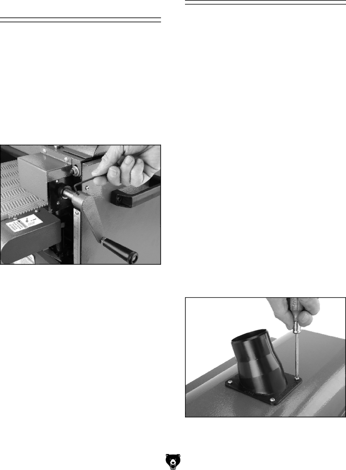
The crank handle is installed on the front right lift screw shaft, and is held in place with two set screws already threaded into the handle.

To mount the handwheel:

1.Place the crank handle over the shaft shown in Figure 6 and, using a 3mm hex wrench, secure the handle with the two set screws.

Figure 6. Crank handle installation.

G0459 12" Drum Sander

Dust Collection

Components and Hardware Needed:

Qty

Dust Hoses 212" (not included)

Length Varies

Hose Clamps (not included)

Varies

Dust Collection System (not included)

1

This drum sander requires a minimum of 400

CFM AT THE DUST PORT.

Note: Do not confuse this CFM recommendation with the rating of the dust collector. To determine the CFM at the dust port, you must take into account many variables, including the rating of the dust collector, the length of hose between the dust collector and the machine, the amount of branches or wyes, and the amount of other open lines throughout the system.

A fine layer of dust will be present on your stock as it comes out of the sander. This is normal.

To connect the dust port to a dust collector:

1.Remove the four Phillips head screws at the dust port hole.

2.Place the 212" dust port over the top cover mounting holes and secure with the Phillips head screws removed in Step 1 as shown in Figure 7.

3.Attach a 212" dust collection hose to the dust port and secure it with a hose clamp.

Figure 7. Dust port installation.

4.Connect the sander to the power source.

-13-

Image 15
Contents Model G0459 Drum Sander Safety Label Placement Table of Contents Warranty and Returns Introduction ForewordContact Info Machine Data Sheet Identification Safety Instructions for Machinery SafetyAlways Lock Mobile Bases if Used Before Operating Machinery Additional Safety for Drum Sanders 110V Operation Circuit RequirementsUnpacking SET UPSet Up Safety Items Needed for Set UpWorking Clearances InventorySite Considerations Floor LoadTo mount the drum sander to a bench top Placing SanderMounting Components and Hardware Needed QtyTo connect the dust port to a dust collector Installing Crank HandleDust Collection To mount the handwheelTest Run Recommended AdjustmentsOperation Safety Switch/Lockout To turn the switch on and OFFOperations To adjust the conveyor speed Depth of Cut Variable SpeedTo set the depth of cut Sanding Sanding TipsTo sand a workpiece Paper Replacement Choosing SandpaperGrit Class Usage H1300 H1298 G7984 H2347 H0736 AccessoriesPRO-STICKSanding Pad Size ModelG7313-Tool Table G3124-Wire Hose Clamps 21⁄2 G3123-Flexible Hose 21⁄2 xG3119-4 x 21⁄2 Adapter G1163-1HP Dust CollectorLubrication MaintenanceCleaning ScheduleTable lift screws Service TroubleshootingMotor & Electrical Sanding Operations Increase pressure roller pressure Belt Service Gauge BlocksTension To align the pulleys Removal/ReplacementTo adjust V-belt tension Pulley AlignmentTo tension the conveyor Conveyor Tensioning TrackingTensioning TrackingDrum parallel to conveyor belt G0459 12 Drum Sander Drum AdjustmentsDrum perpendicular to feed direction To adjust the pillow block bearingsHeight Factory SettingTo adjust the pressure rollers to the factory setting Pressure RollerTo calibrate the scale pointer Scale Pointer CalibrationTable Lift Screws To adjust the table lift screwsTo replace the conveyor belt Conveyor Belt ReplacementTo Step Drum sander disassembled to StepBrass Shims Page Page Feed Motor Capacitor Motor WiringSwitch Box Wiring Electrical ComponentsWiring Diagram Frame Parts Breakdown Drum and Conveyor Parts Breakdown Description Parts ListDust Scoop 214 215 213 212 216 217 209 218 Safety Label Placement and Parts ListWarranty and Returns Comments Warranty CardBOX BELLINGHAM, WA Grizzly INDUSTRIAL, INCPage Call Today For a Free Full Color Catalog