Maintenance & Service Guide
Presario 1900 Series
Models: 1900T, 1905, 1906, 1910, 1915, 1919, 1920, 1922, 1925, 1926, 1927, 1928, 1929, and 1930
Before You Begin |
| Specifications |
| Parts Catalog |
|
|
|
|
|
Removal Sequence |
| Troubleshooting |
| Battery Operations |
|
|
|
|
|
|
|
|
|
|
Product Description |
| Pin Assignments |
| Index |
|
|
|
|
|
Removal and Replacement Procedures
Electrostatic
Discharge
Service
Considerations
Cables and
Connectors
Preparing the
Computer for
Disassembly
![]() Battery Pack
Battery Pack
![]() Hard Drive
Hard Drive
![]() Keyboard
Keyboard
Memory
Module
![]() Modem
Modem
![]() Heatspreader
Heatspreader
![]() Processor
Processor
Display Panel
Assembly
Upper CPU
Cover with
Palmrest and
TouchPad
Hard Drive/
Battery
Charger Board
Converter
Board
Low Voltage
Differential
Signal Board
![]() Fan Assembly
Fan Assembly ![]()
![]() System Board
System Board ![]()
Speaker
Assembly
Disassembling
the Wedge
DVD or CD
Drive
System to
Wedge
Interface
Board
![]() Diskette Drive
Diskette Drive ![]()
Wedge to Port
Replicator
Interface
Board
How to use
Processor Jig
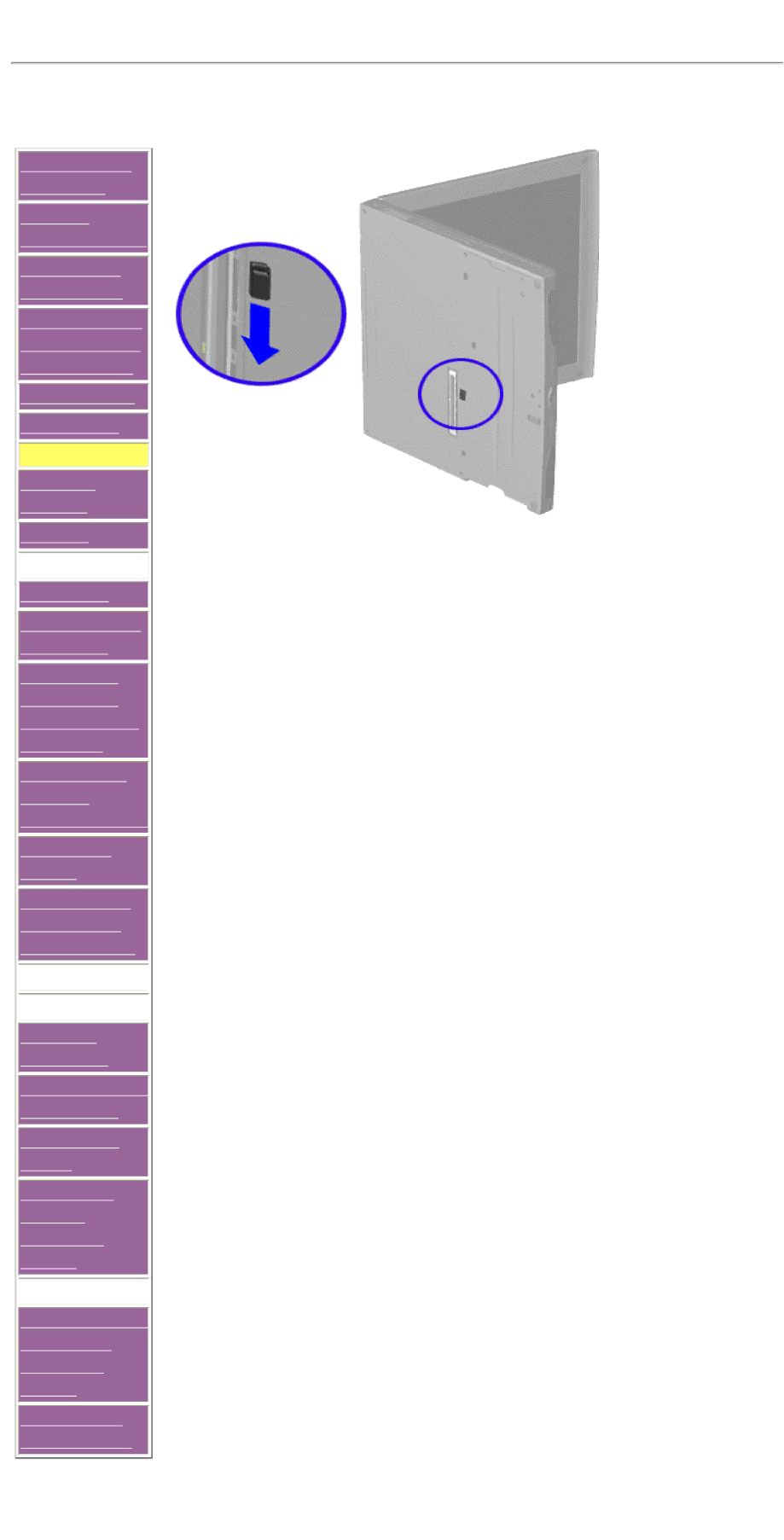
Removing the Keyboard
To remove the keyboard, complete the following steps:
1.Prepare the computer for disassembly.
2.Partially close the unit and place it on its side.
3.Slide the keyboard eject switch located in the center of the bottom of the unit to the right to release the keyboard.
Next Step