HP 1660 manual Bracket, reverse the previous steps

Page 54

Maintenance & Service Guide

Presario 1660 Model

MSG Index Home Page Notice Preface Product Description Troubleshooting Illustrated Parts Catalog Removal & Replacement Procedures Specifications Pin Assignments Battery Pack Operations

Removing the Hard Drive (continued)

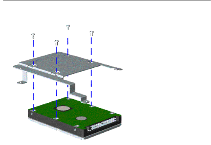
To remove the hard drive mounting bracket, remove the screw from each corner.

To replace the hard drive and hard drive mounting

bracket, reverse the previous steps.

Return to Removal &

Replacement

Procedures

Image 54
Contents Maintenance & Service Guide Maintenance & Service Guide Presario 1660 ModelSymbols PrefaceProduct Description CompaqTroubleshooting Follow the Preliminary StepsIllustrated Parts Catalog Removal and Replacement Procedures Serial Number LocationConnector Pin Assignments Parallel Connector Pin SignalBattery Pack Operating Time Increasing Battery Pack Operating TimeModels and Features Controls and Lights Front Bezel Buttons Front Bezel Lights Left Side Components Right Side Components Bottom of Unit Rear Connectors Power Management for Windows Power Management SettingsPreliminary Steps Run Computer CheckupClearing the Power-on Password Power-On Self Test Post Running PostCompaq Diagnostics Computer SetupContacting Compaq Support Shipping PreparationDiagnostic Error Codes ProceduresDiagnostic Error Codes Hard Drive Test Error CodesTroubleshooting Without Diagnostics Before Replacing PartsSolving Minor Problems Audio ProblemsSolving Minor Problems Display ProblemsSolving Minor Problems Illustrated Parts Catalog Illustrated Parts Catalog Illustrated Parts Catalog Removal and Replacement Procedures Electrostatic Discharge Generating StaticService Considerations Cables and Connectors ZIF Connectors Back to Cables Connectors Back to Cables and Connectors Ribbon cable position for the diskette drive Back to Cables Connectors Preparing the Computer for Disassembly Removing the Battery Pack Return to Removal Replacement Procedures Removing the Palmrest Assembly Prepare the computer for disassemblyRemoving the Palmrest Assembly Removing the Palmrest Assembly Removing the Keyboard and Heatspreader Next step Return to Removal Replacement Procedures Removing the Processor To reinsert the processorRemoving the Hard Drive Removing the mounting bracket Bracket, reverse the previous steps Removing the Upper CPU Cover Removing the DVD Drive Removing the DVD Drive Removing the Battery Charger Board Removing the Modem To replace the modem, reverse the previous steps Removing the Display Panel Assembly Slide the cable out of the connector cable guide Removing the Display Panel Assembly Removing the Display Panel Assembly Return to Removal Replacement Procedures Removing the Speaker Assembly Removing the Diskette Drive SpeakersReturn to Removal & Replacement Procedures Removing the Fan Assembly Removing the System Board Return to Removal Replacement Procedures Remove the two long standoff nuts from the system board Removing the System Board Remove four screws from the system board Removing the System Board Return to Removal & Replacement Procedures Removing the Memory Module Return to Removal Replacement Procedures Specifications Physical and EnvironmentalSpecifications System I/O AddressDiskette Drive Illustrated Parts Catalog Illustrated Parts Catalog AC Power Cord Miscellaneous Hardware Kit Spare Part Number Other parts not shown Description
Related manuals
Manual 14 pages 60.01 Kb Manual 140 pages 50.13 Kb