Quadra-Fire 4300 WOOD STOVE SERIES installation instructions Installation of Optional BLOWER, Part

Page 18

R

4300 ACT Wood Stove Series

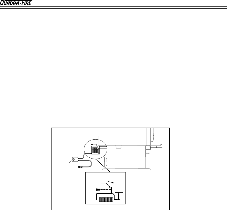
INSTALLATION OF OPTIONAL BLOWER, Part 831-1701

The blower is shipped fully assembled and ready for installation.

1.Remove the three bolts (1/4”-20 Phillips Head) on the outer skin at the bottom rear of stove.

2.Align holes in mounting flange of blower with bolt holes in stove. Blower should be positioned around bottom of rear outer skin as shown in drawing below.

3.Re-insert and tighten bolts, securing blower onto outer wall of stove.

Do not remove ground from plug. Plug blower cord into a grounded outlet. Route power cord away from stove in such a manner to avoid heat from the stove, traffic, or other damage. Do not route cord under or in front of stove.

ADJUSTING THE BLOWER SPEED CONTROL, IF NECESSARY*

*The blower speed control for this unit is adjusted at the factory and normally does not

require further adjustment.

NOTE: When the speed control is turned clockwise, it will click on to high speed. Continue to turn the speed control clockwise to decrease the speed. At full clockwise, the blower should blow gently, but should not stop.

1.With the unit plugged in, turn the speed control knob to slow (full clockwise).

2.With a small screwdriver, adjust the blower speed by turning the adjustment mechanism through the hole on the side of the speed control.

3.Adjust the speed so the blower runs slowly, but does not stop. Turn clockwise to slow the blower and counterclockwise to increase the speed.

BLOWER SPEED CONTROL


Blower

Outer

Skin

Mounting


Flange


Figure 17A

(4300 Millennium Only)

TOP HEAT SHIELD INSTALLATION, Part: 831-0972

1.

Unscrew and remove the rear heat deflector.

3.

Set top heat shield on stove and push down into


2.

Attach the two “S” clips to the upper edge of the outer


“S” clips.


4.

Install chimney pipe through the hole in the top


wall of the stove.


heat shield.


Page 18

250-7061C December 10, 2004

Image 18
Contents Wood Stove Series ACT Wood Stove Series Table of Contents Listings & Safety Cautions Installation Materials Needed for SafetyDimensions Step TOP UNI-BODY Pedestal Model Vent Specifications Locating Your StoveClearances to Combustibles UL and ULC Both Models Floor ProtectionUSA -4300 Millinneum USA 4300 Uni-Body Step Top USA Required Canada RecommendedACT Wood Stove Series Floor Protection Cont’d Alternate Materials WorksheetChimney HEIGHT/DRAFT Flue Systems Masonry Chimney Cont’dMasonry Chimney Solid Pack Chimney with Metal Supports AS a Thimble Masonry Connection to a Metal PRE-FABRICATED Chimney Interior ChimneyMobile Home Installation LEG Model ASH Removal System ARS InstallationARS Operating and Cleaning Pedestal ModelPedestal or LEG KIT Installation Pedestal Model LEG ModelInstallation of Optional BLOWER, Part Millennium Only TOP Heat Shield INSTALLATION, PartAdjusting the Blower Speed CONTROL, if Necessary Outside AIR KIT Installation PartOperating Instructions AIR ControlsACT Wood Stove Series Operating Instructions Cont’d Building a FireWood Selection and Storage OpacityBurn Rates Blower Operating InstructionsFirebrick Chimney CleaningCreosote Glass CareBrick Replacement Instructions Glass ReplacementPart Replace with 5mm ceramic glass only Door Handle Assembly Baffle Removal and InstallationSpring Handle Warning DOOR, Glass and Door Handle Assembly Exploded ViewsModel Shown Step Top Uni-Body Appliances AccessoriesService Parts MillenniumACT Wood Stove Series ACT Wood Stove Series Service and Maintenance Log Lifetime Warranty Contact Information