SECTION I - GENERAL DESCRIPTION AND CONSTRUCTION
GENERAL DESCRIPTION
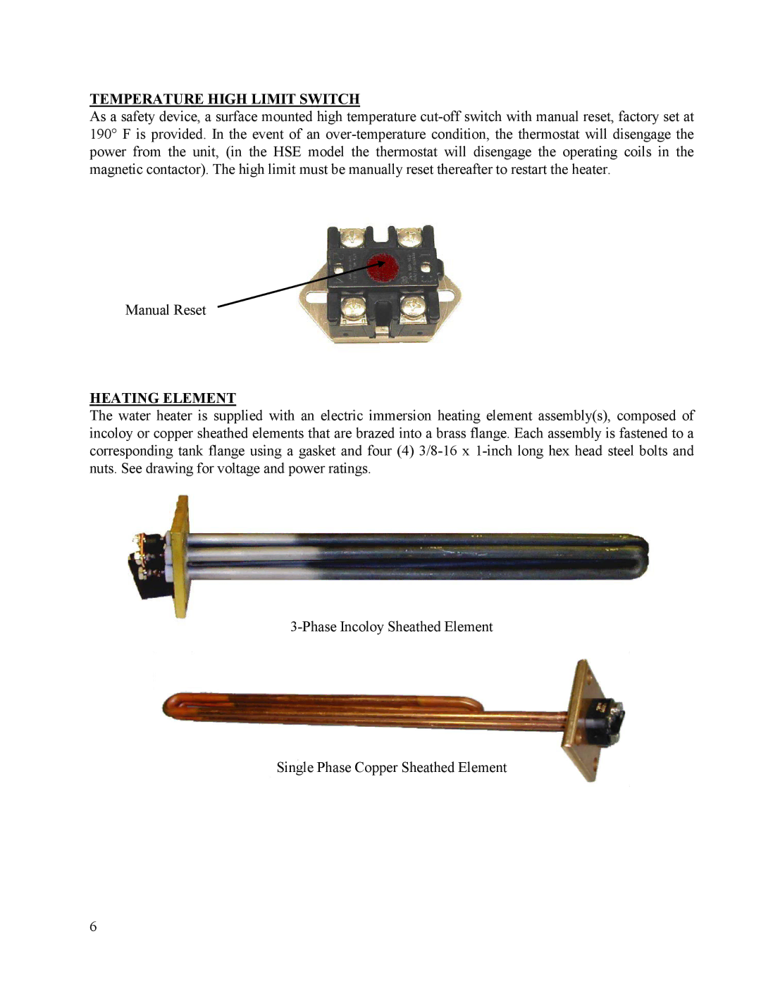
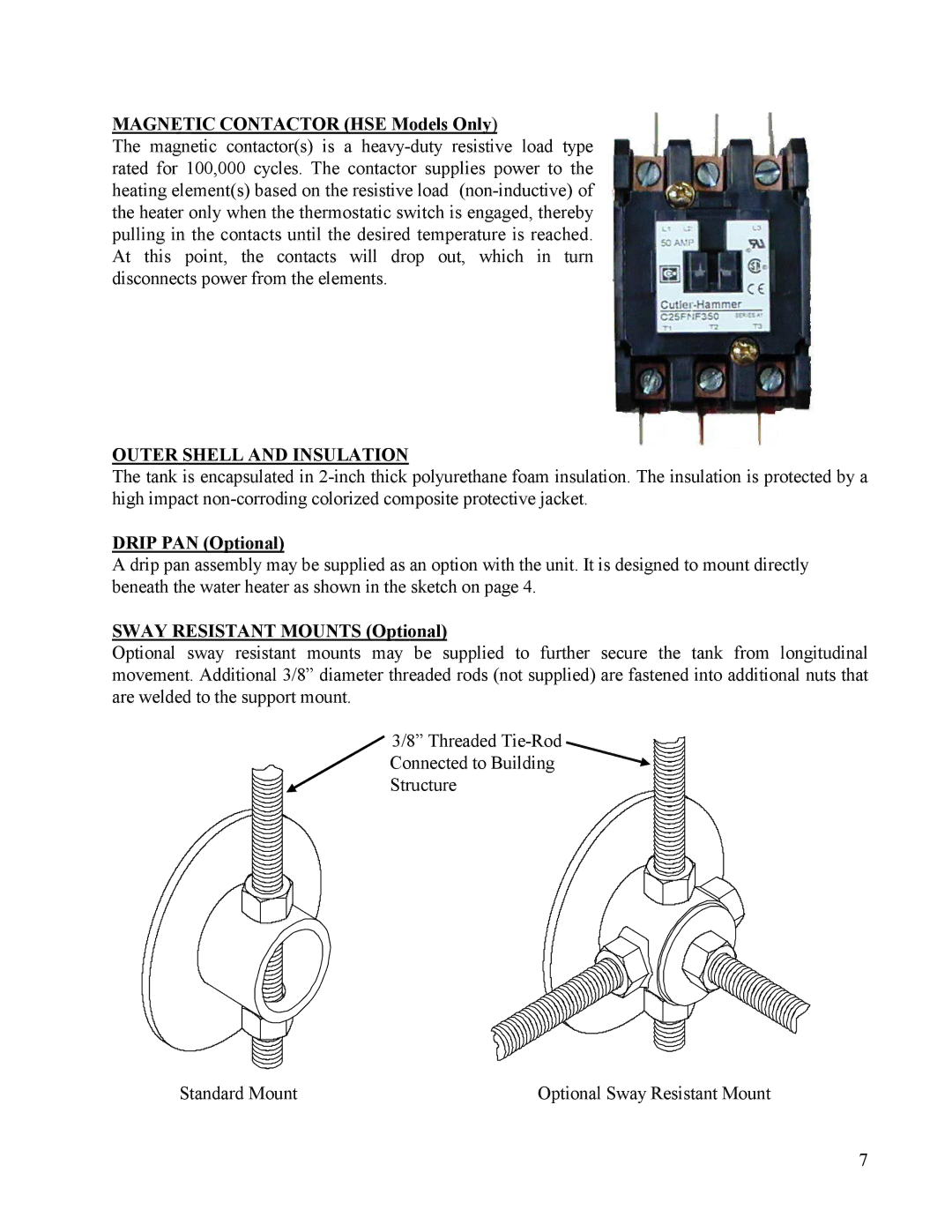
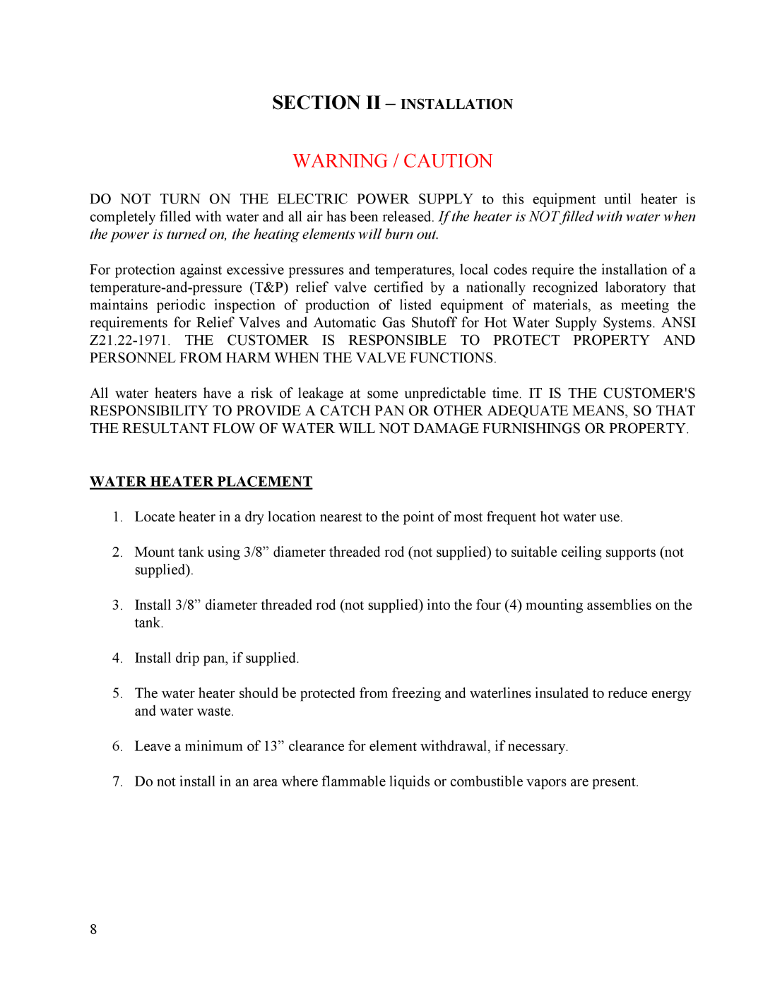
This book describes a packaged electric water heater that is a stationary, self-contained unit. The complete assembly consists of the storage tank, immersion electric heating element(s), thermostat, safety relief valve, safety high temperature cut out, and any other required electrical operating control. Optional equipment may be supplied with your unit. Please consult the product drawing for details specific to your assembly. The unit is factory assembled, insulated, jacketed, wired, tested, and ready for electrical and plumbing service connections.
CONSTRUCTION
TANK
The standard storage tank is constructed of steel and internally lined with specially formulated Hydrastone cement to a ½-inch minimum thickness. The tank is designed for a maximum allowable working pressure of 150 psi (300 psi TP).
TANK CONNECTIONS
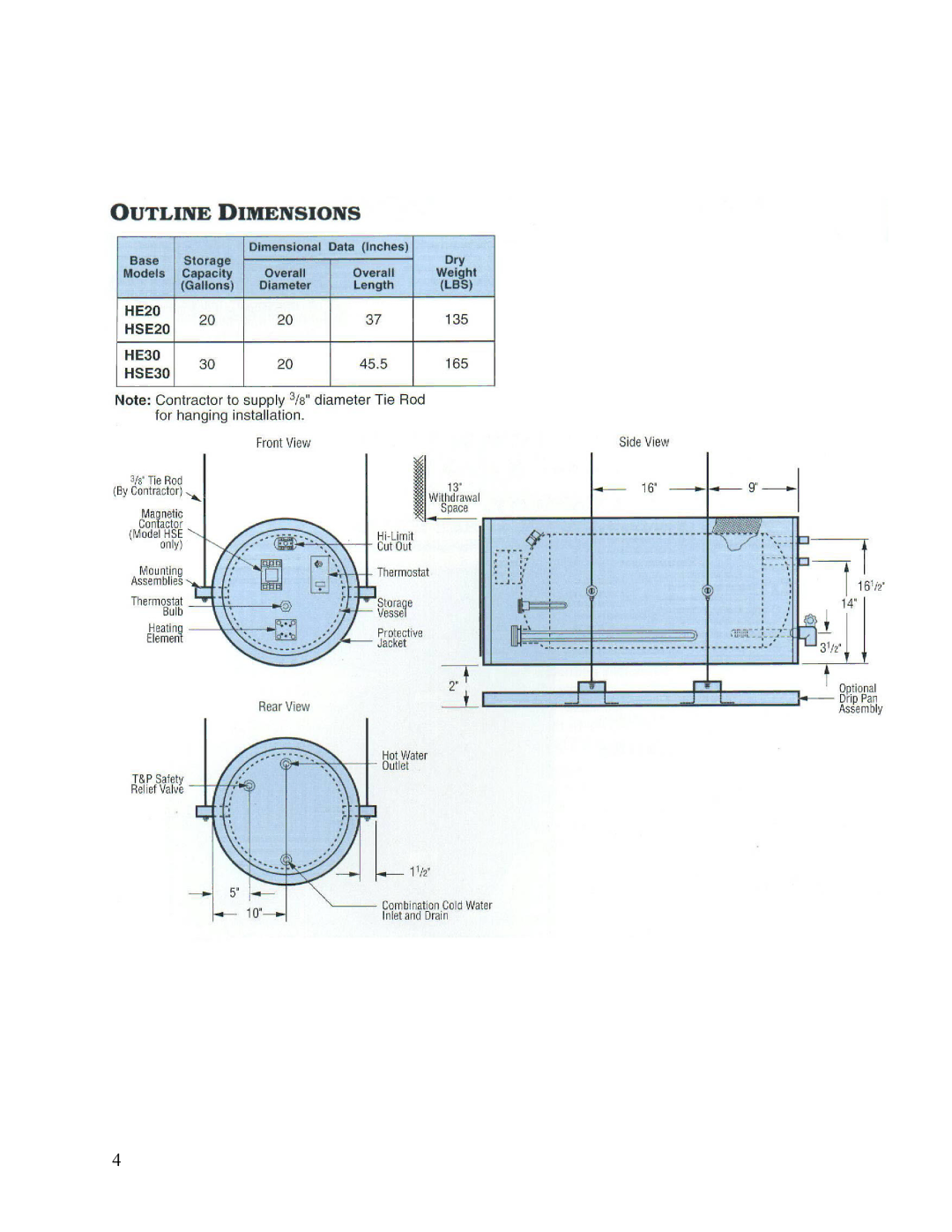
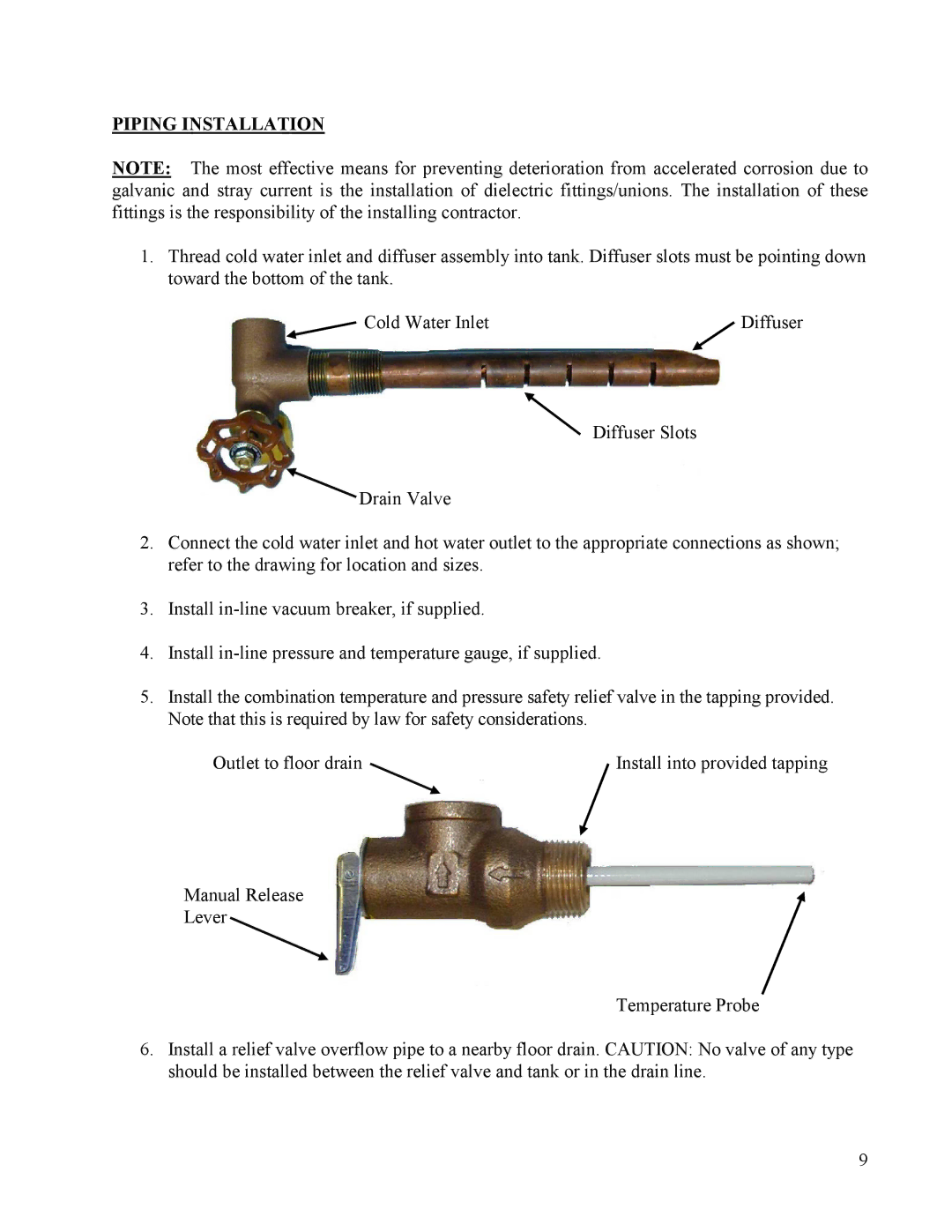
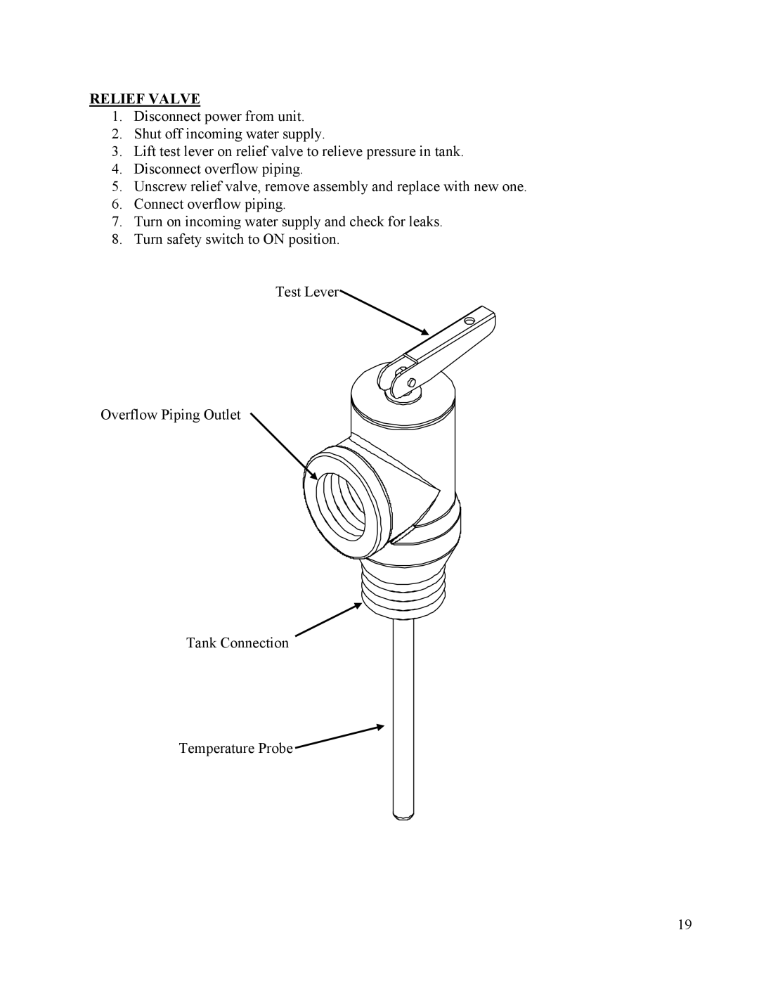
The heater is supplied with separate cold water and hot water connections. Water entering the cold water inlet is deflected by means of a baffle within the tank. A ¾-inch FNPT connection is located on the side of the heater for mounting a combination safety temperature and pressure relief valve. An overflow line should be utilized from the relief valve outlet to a floor drain. A ¾-inch GHT connection is supplied for draining. See drawing for locations and sizes.
CONTROL THERMOSTAT
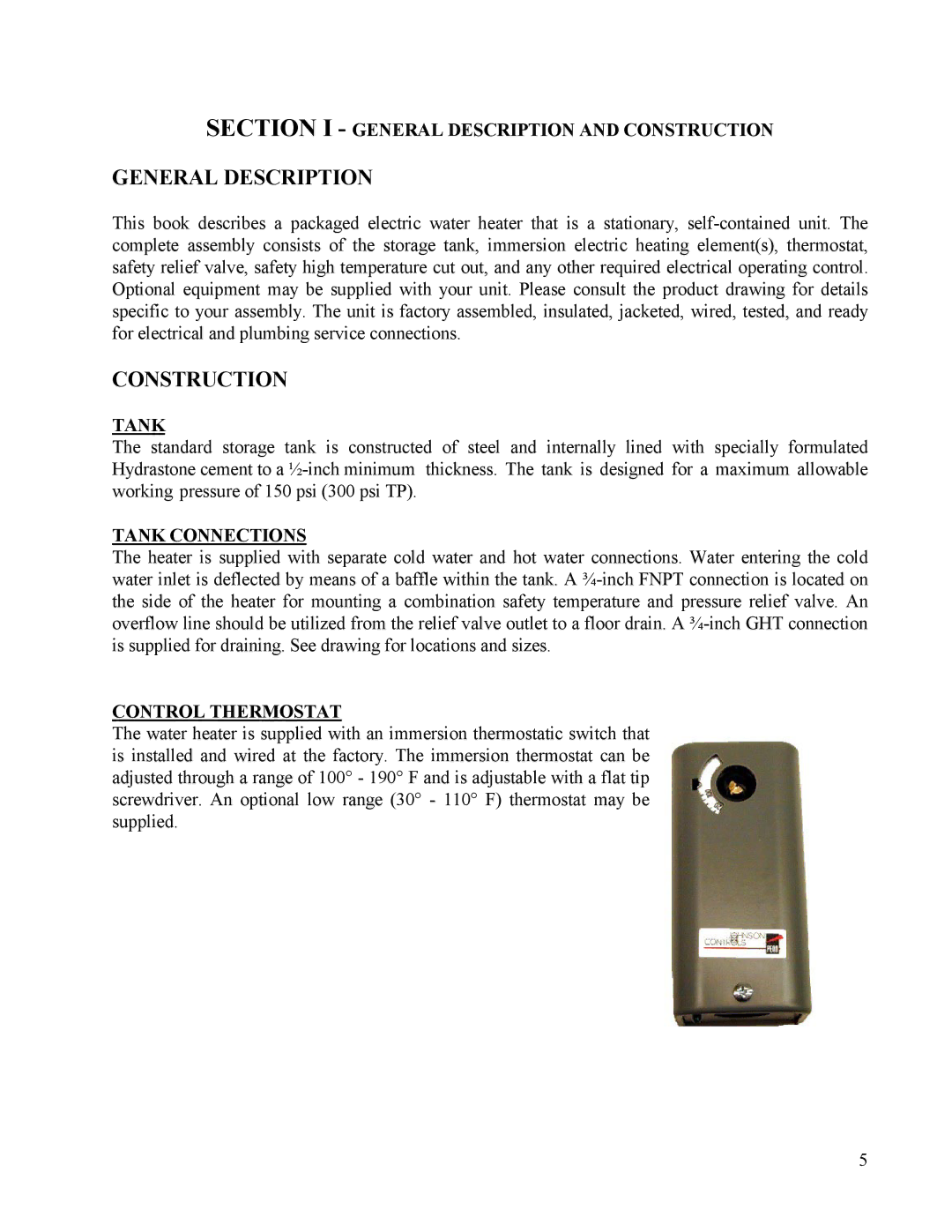
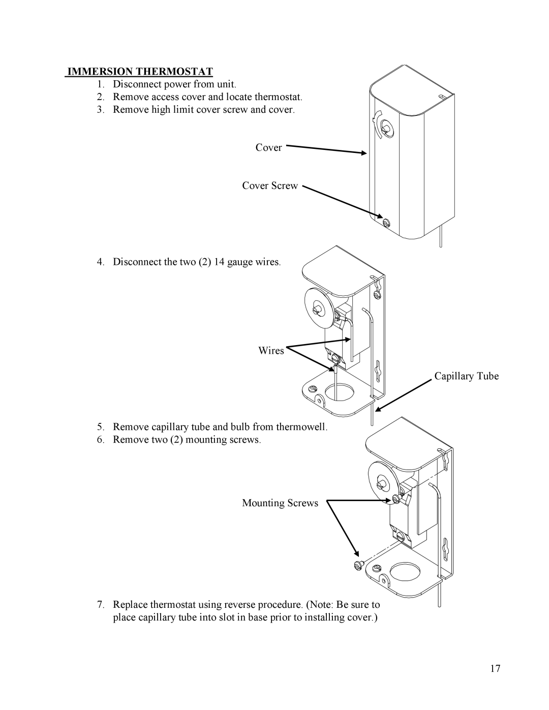
The water heater is supplied with an immersion thermostatic switch that is installed and wired at the factory. The immersion thermostat can be adjusted through a range of 100° - 190° F and is adjustable with a flat tip screwdriver. An optional low range (30° - 110° F) thermostat may be supplied.
5

