Desa Tech CGG3630P, CGG2618P, CGG3324PT Optional Positioning of Thermostat Sensing Bulb

Page 22

UNVENTED (VENT-FREE) GAS LOG HEATER

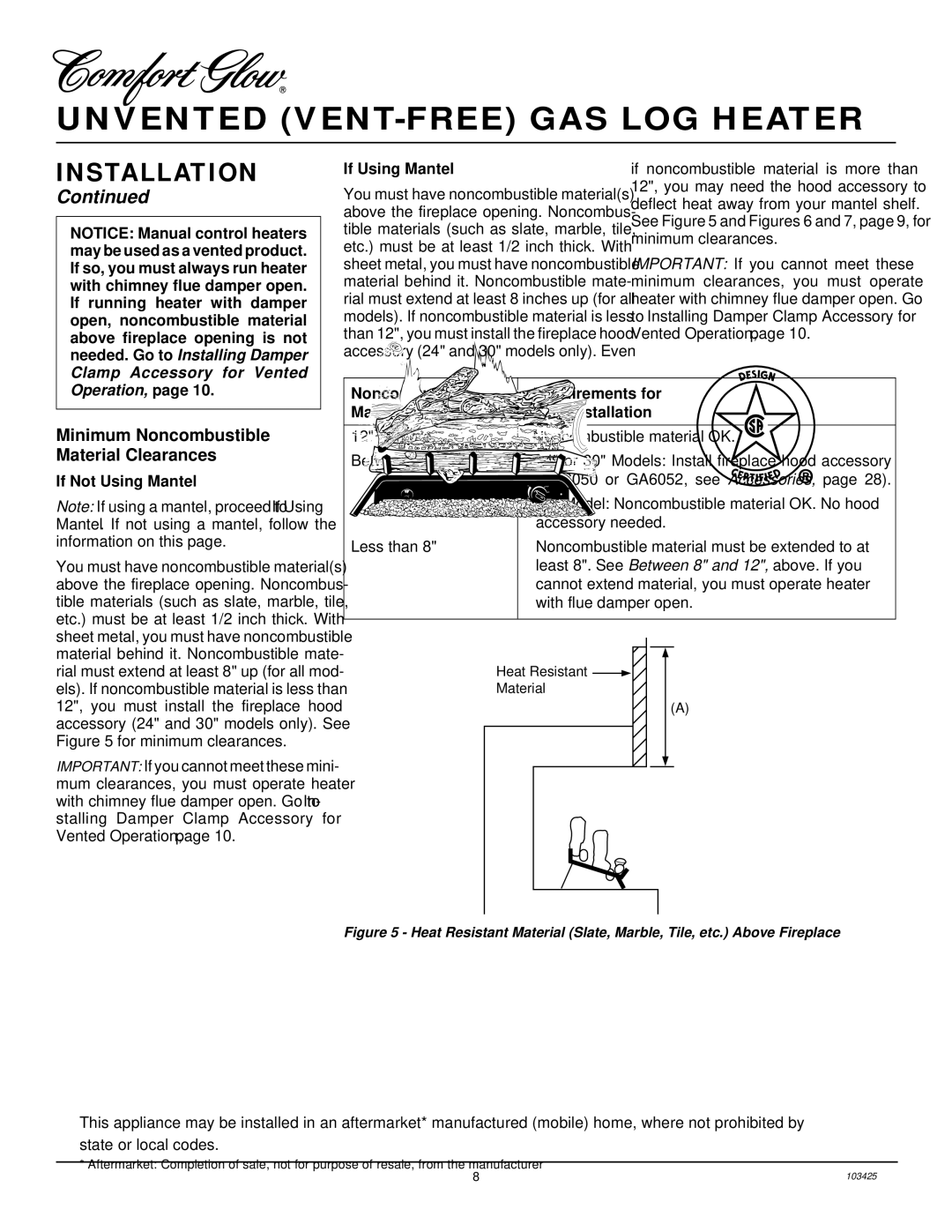
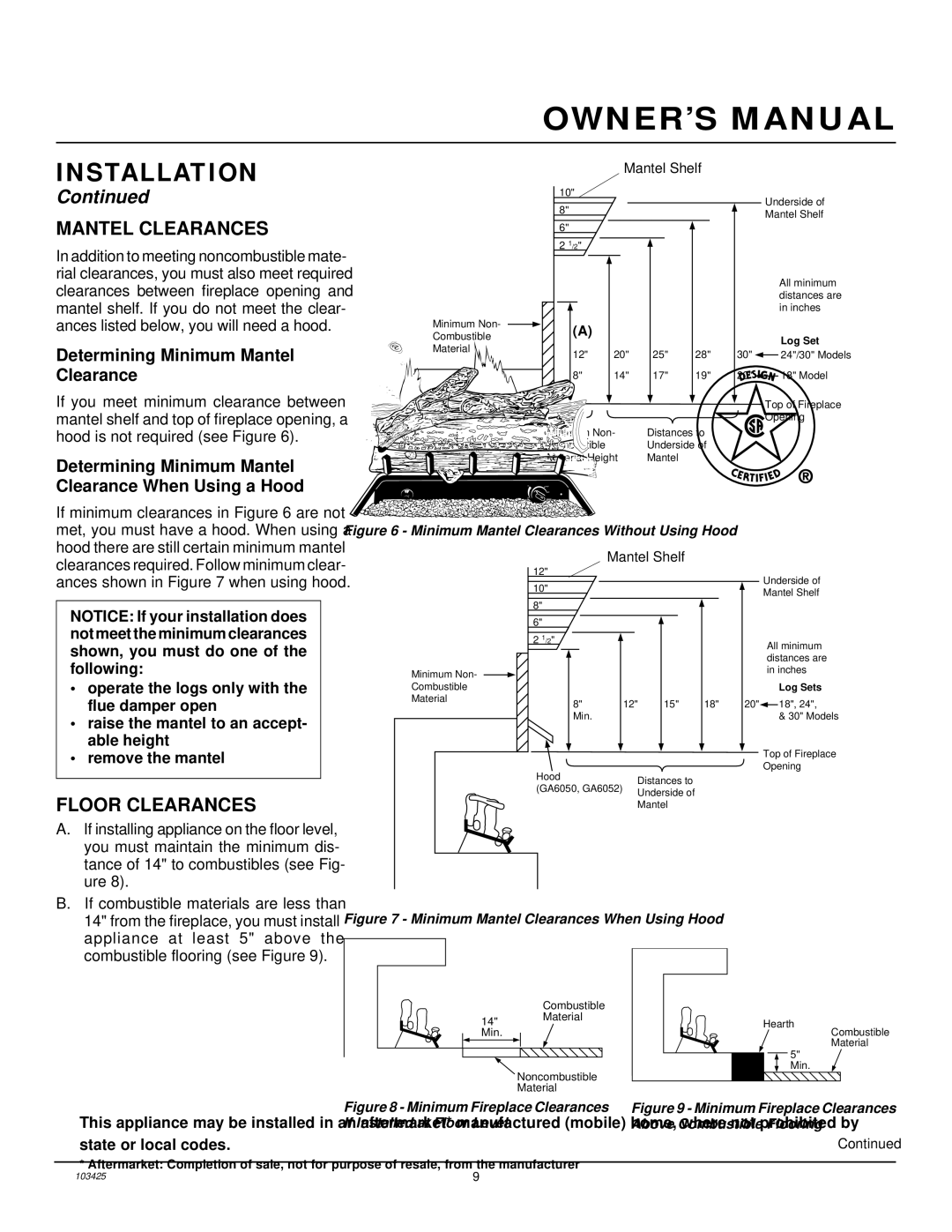
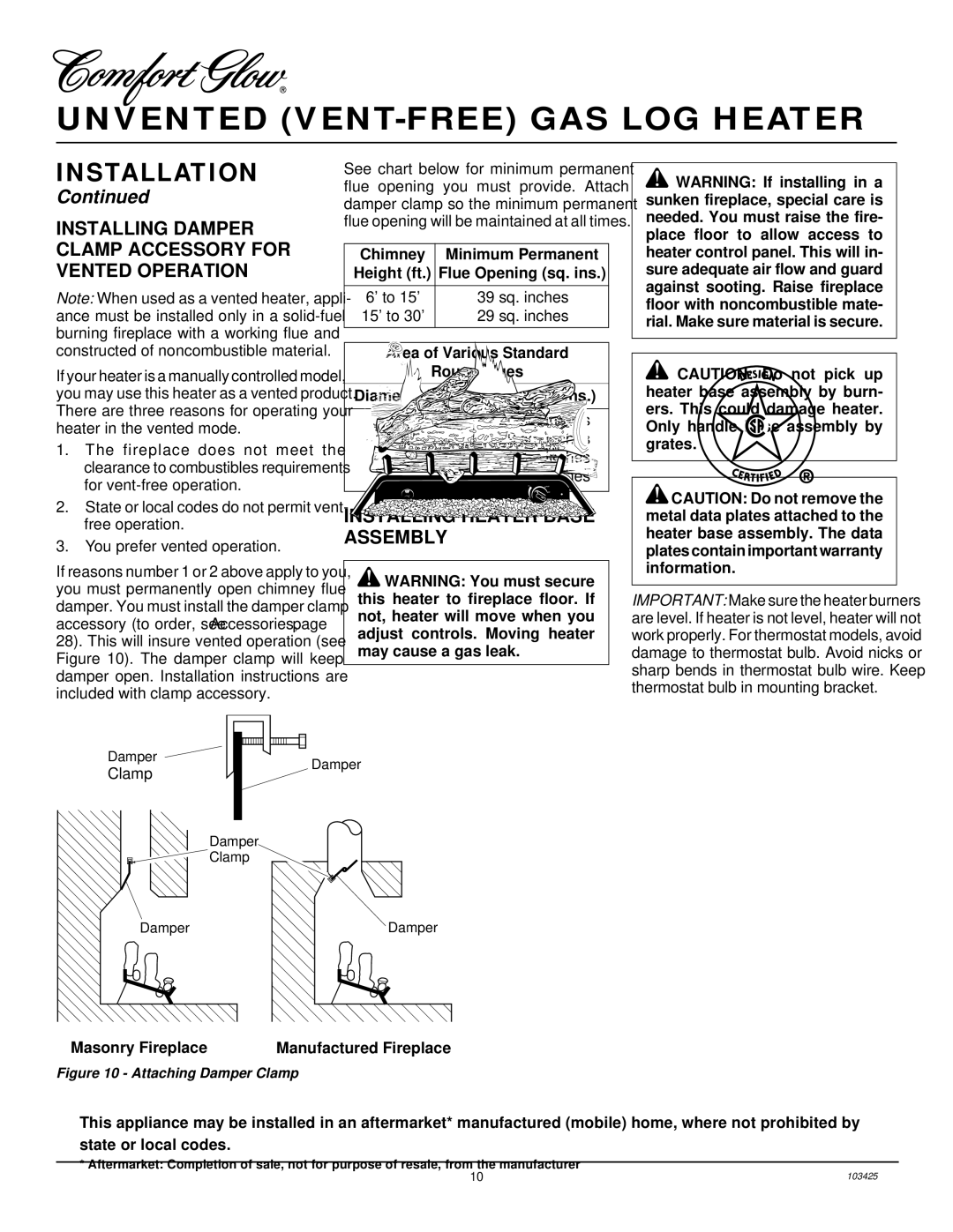
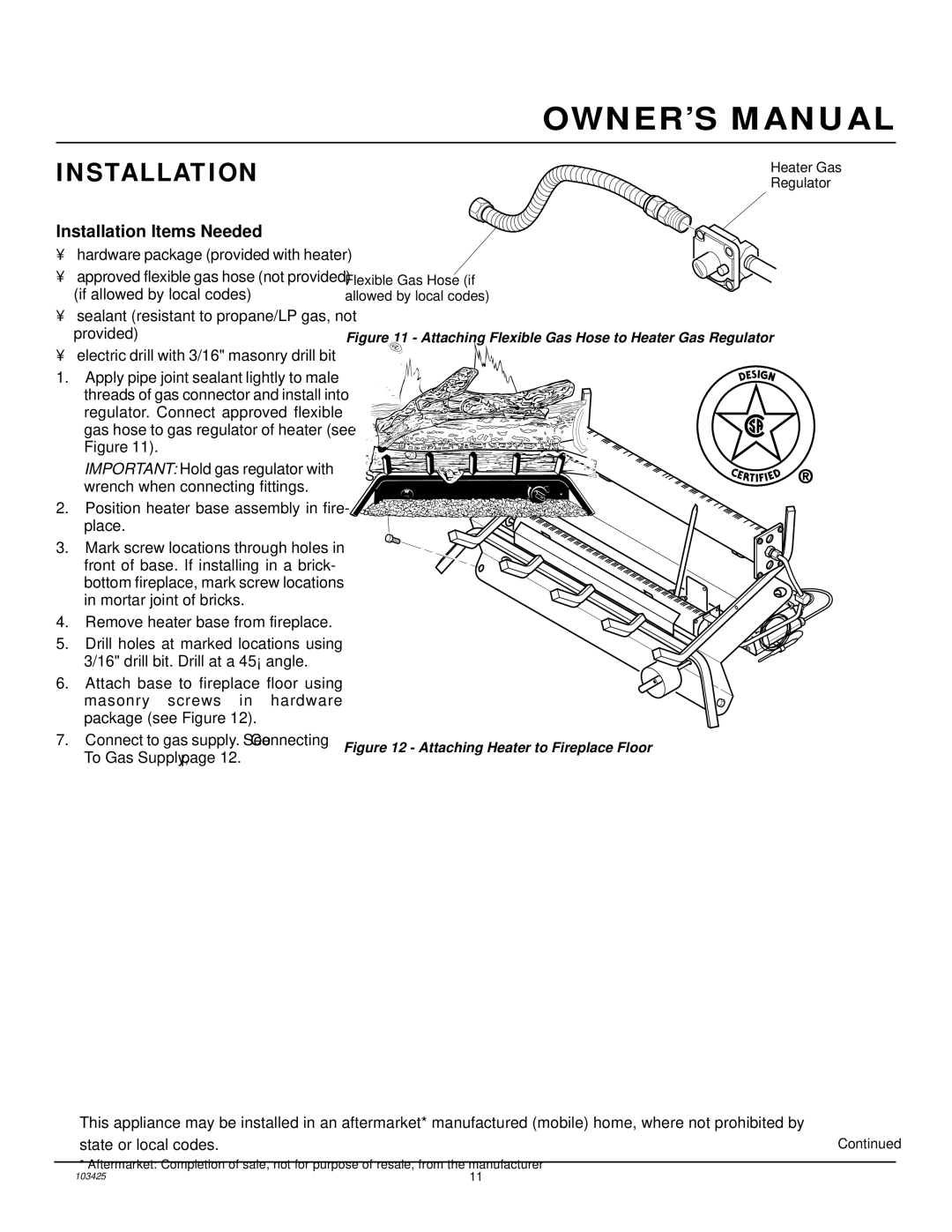
OPTIONAL POSITIONING OF THERMOSTAT SENSING BULB

FOR MASONRY AND FACTORY-BUILT METAL FIREPLACE

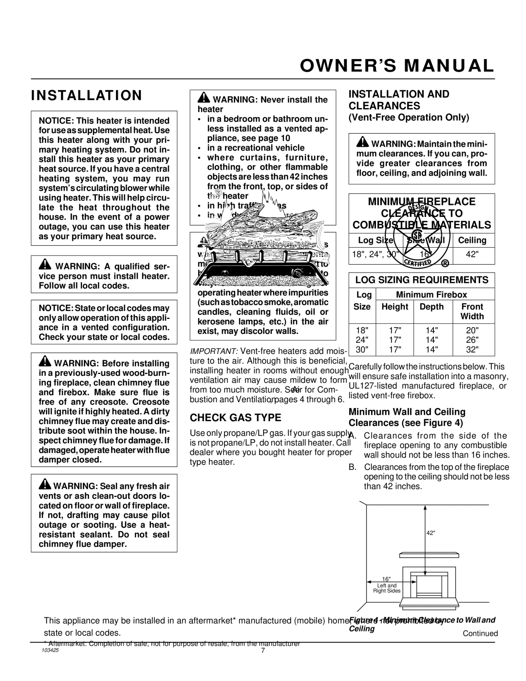
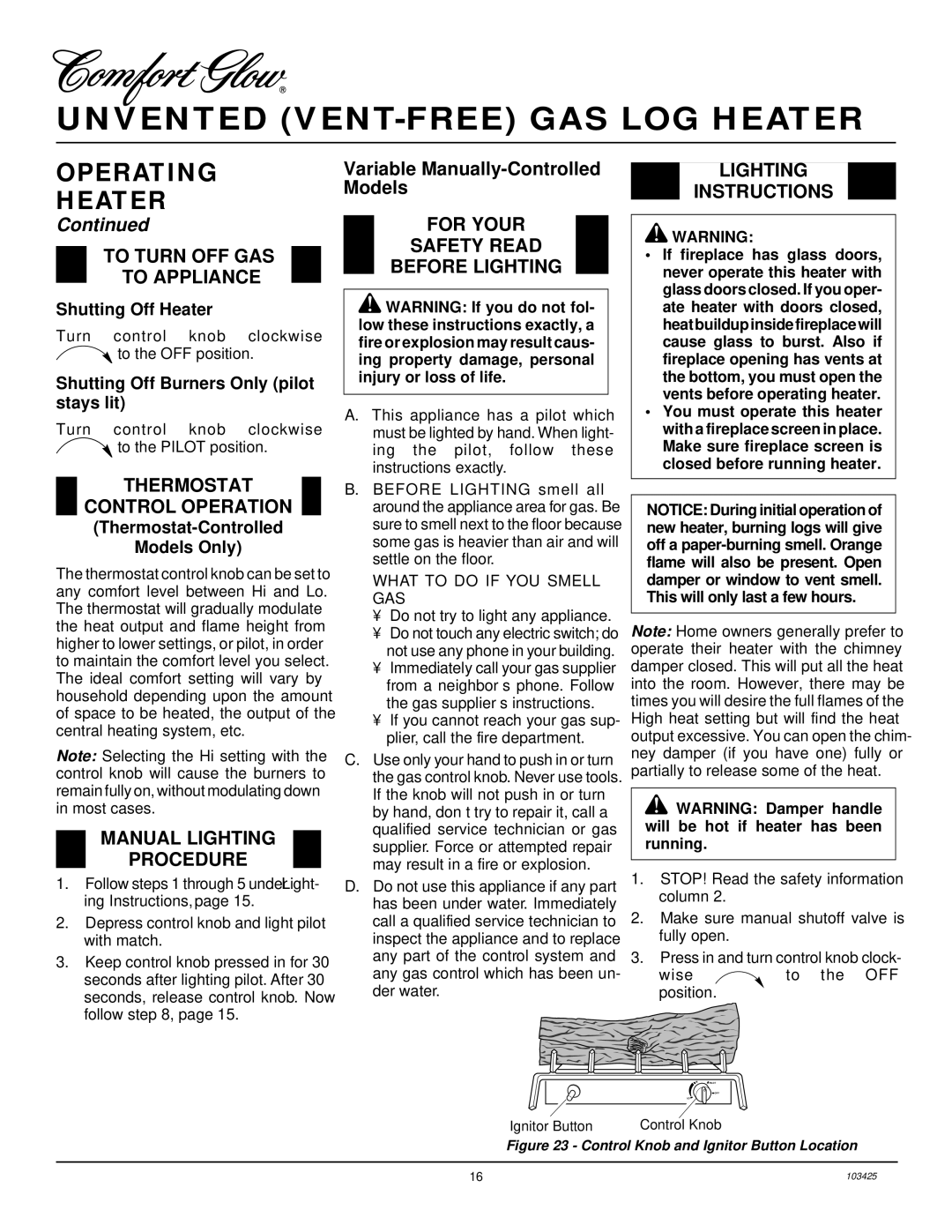
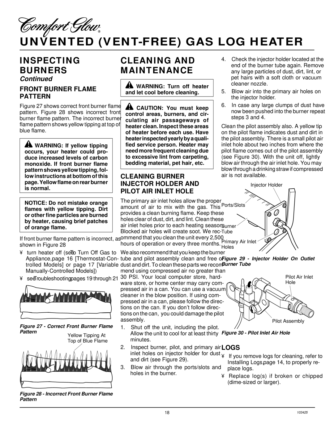
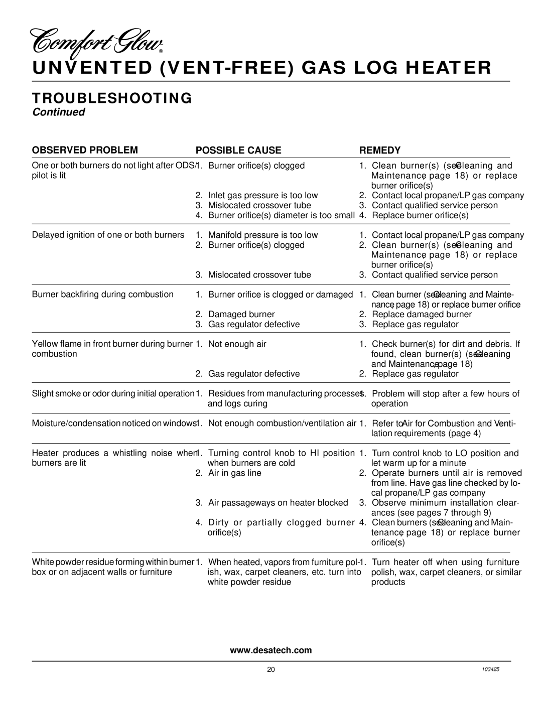
If your log set cycles to pilot, but the room temperature drops to a lower than ideal comfort level before the log set comes back on, you may want to reposition the thermostat sensing bulb.

The thermostat sensing bulb is located on the gas valve assembly. This location al- lows the thermostat to keep the room tem- perature at an ideal comfort level for most fireplace applications. For positioning the thermostat sensing bulb elsewhere, an adhe- sive-backed mounting clip is available.

Tools needed:

5/16" hex driver or socket

1.

Locate the gas valve assembly and ther-


mostat sensing bulb (see Figure 31).

2.

With 5/16" hex driver or socket, loosen


the thermostat screw. Carefully slide


the thermostat sensing bulb out of the


retaining clamp (see Figure 33).


Note: Do not remove the screw. Make


sure you tighten the screw after remov-


ing the thermostat sensing bulb.


IMPORTANT: Do not force or bend the


thermostat sensing bulb or capillary. A


crimped capillary will not allow ther-


mostat to operate properly. It cannot be


repaired, the valve must be replaced.

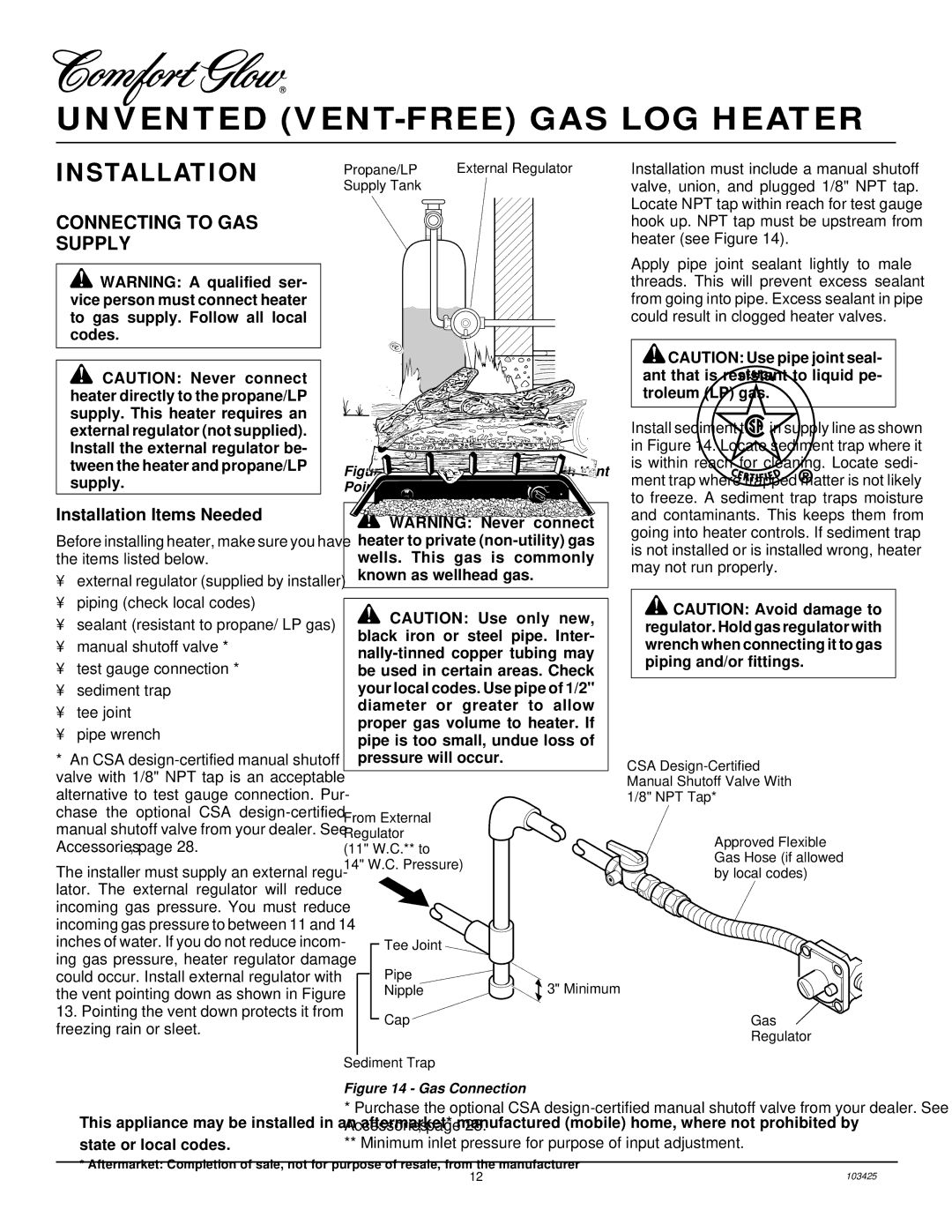
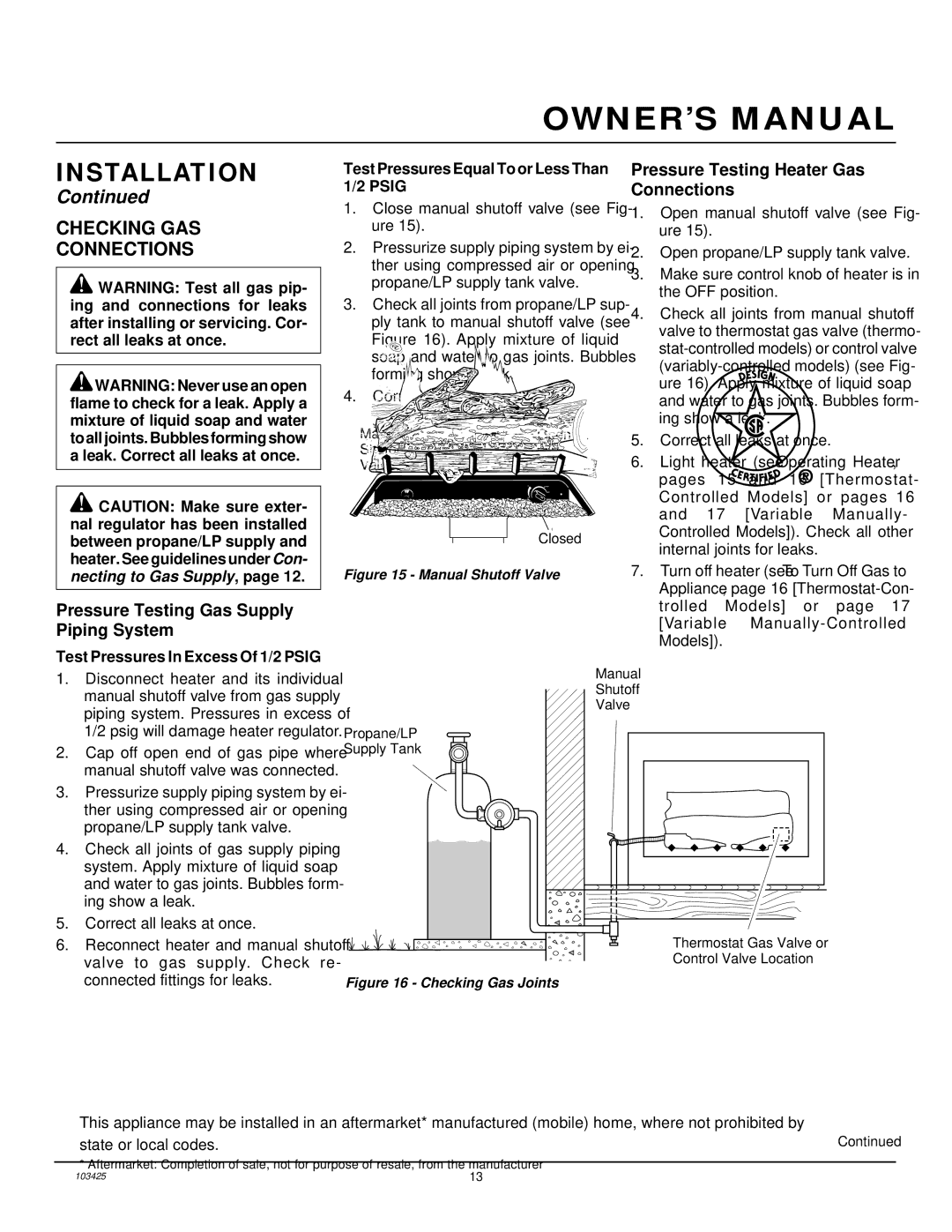
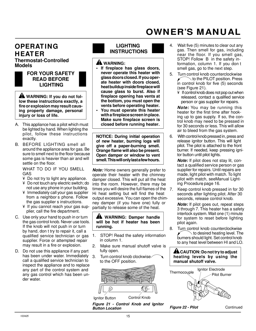
4.The mounting clip must be a minimum of 3" from bottom of fireplace to pre- vent crimping of capillary. Once you have decided on a location, clean the area thoroughly. Remove the paper backing from the adhesive on back of mounting clip. Press the clip into the new location so that the thermostat sensing bulb will be positioned vertically with the capillary at the bot- tom (see Figure 37). Slide the thermo- stat sensing bulb into the clip.

IMPORTANT: Do not crimp capillary.

Gas Valve

Assembly

Thermostat

Sensing Bulb

Figure 31 - Location of Gas Valve Assembly and Thermostat Sensing Bulb

Figure 32 - Adhesive-backed Mounting Clip

Capillary

Thermostat

Sensing Bulb

Adhesive-backed

Mounting Clip

Figure 34 - Locating Thermostat Sensing Bulb on Masonry Fireplace

Thermostat

Sensing

Bulb

Adhesive- backed Mounting Clip

Figure 35 - Locating Thermostat Sensing Bulb on Factory-built Metal Fireplace

Thermostat

Sensing

Bulb

Adhesive-


backed


Mounting


Clip

Glass Doors


Figure 36 - Installing Thermostat Sensing Bulb behind Glass Doors

3. The thermostat sensing bulb may be

located to the lower right front side of

fireplace. Determine location of sens-

ing bulb, but do not mount sensing bulb

until step 5. If you have a masonry fire-

place, see Figure 34 for location.

If you have a factory-built metal fire-

Thermostat

Screw Sensing

Capillary

Thermostat

Sensing

Bulb

Adhesive- backed Mounting Clip

place, see Figure 35 for location.

If your fireplace has glass doors, posi-

tion sensing bulb directly behind door

gap on right bottom side (see Figure 36).

Retaining Bulb

Clamp

Figure 33 - Removing Thermostat Sensing Bulb

Do Not Crimp

Capillary

Figure 37 - Positioning the Thermostat Sensing Bulb in the Vertical Position with the Capillary at the Bottom

22

103425

Image 22
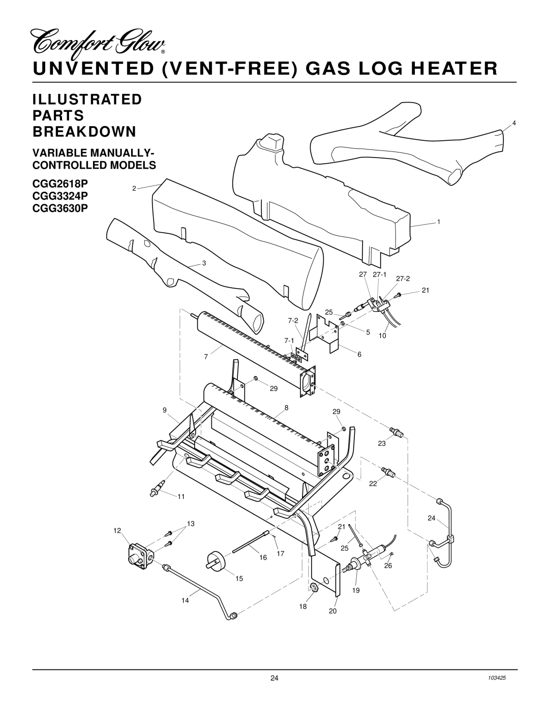
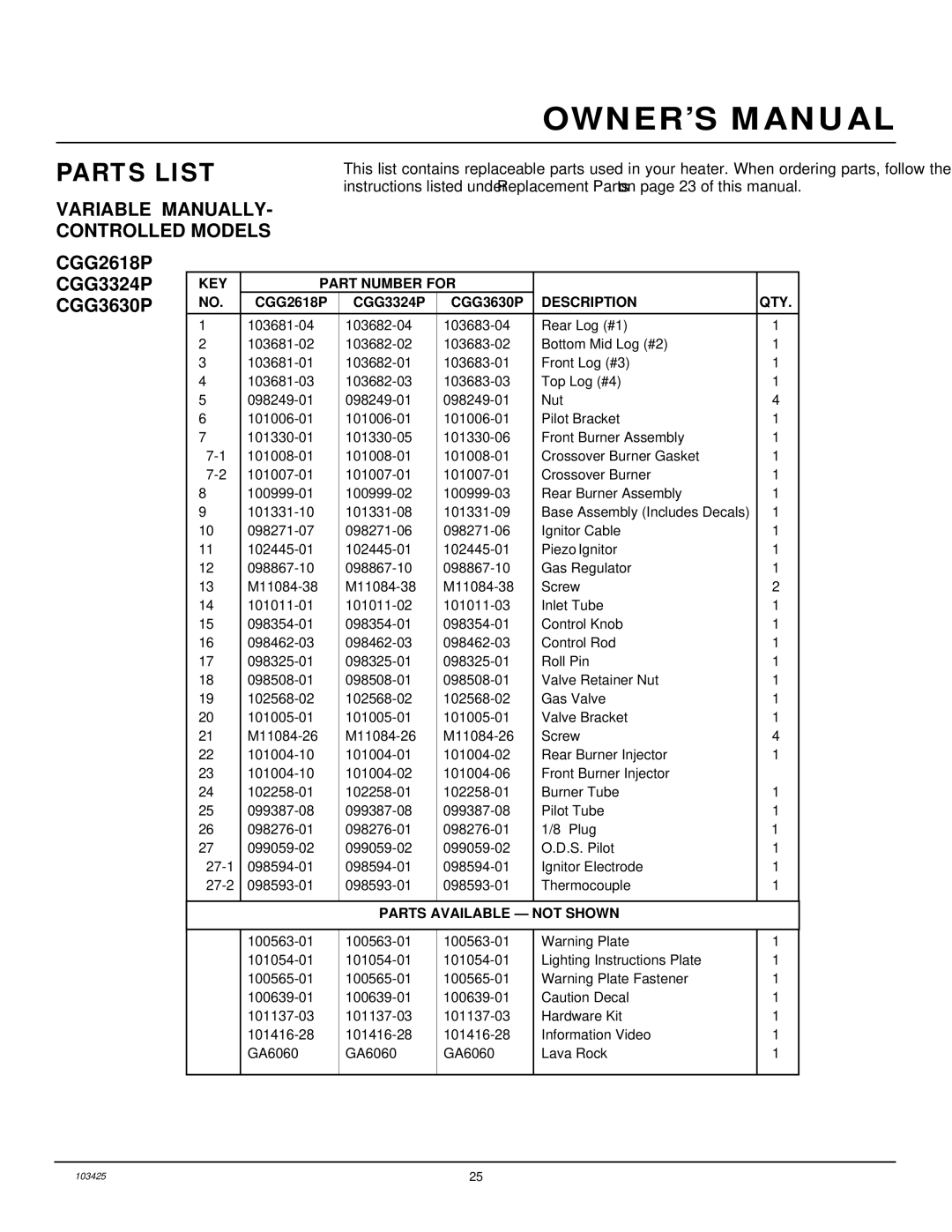
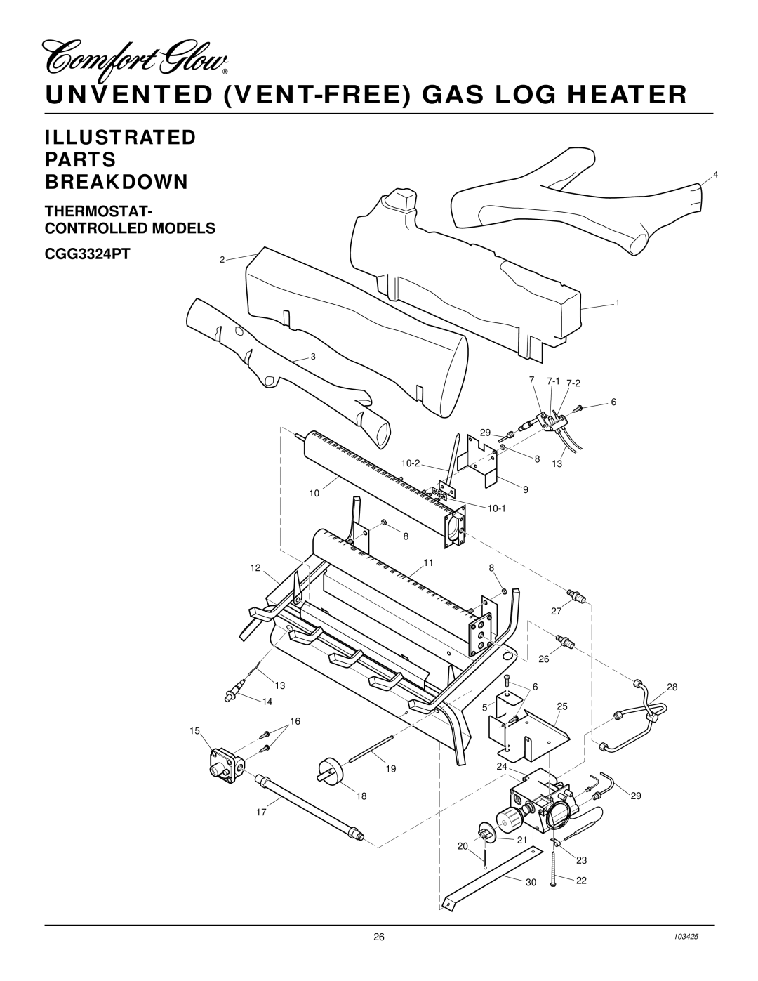
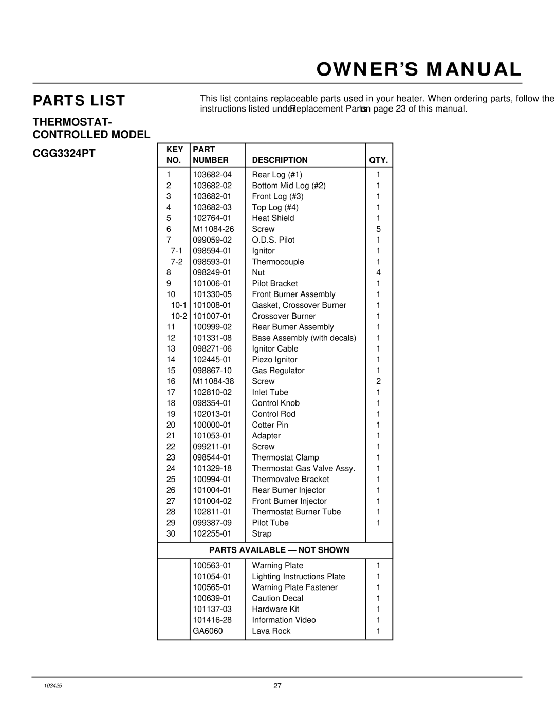
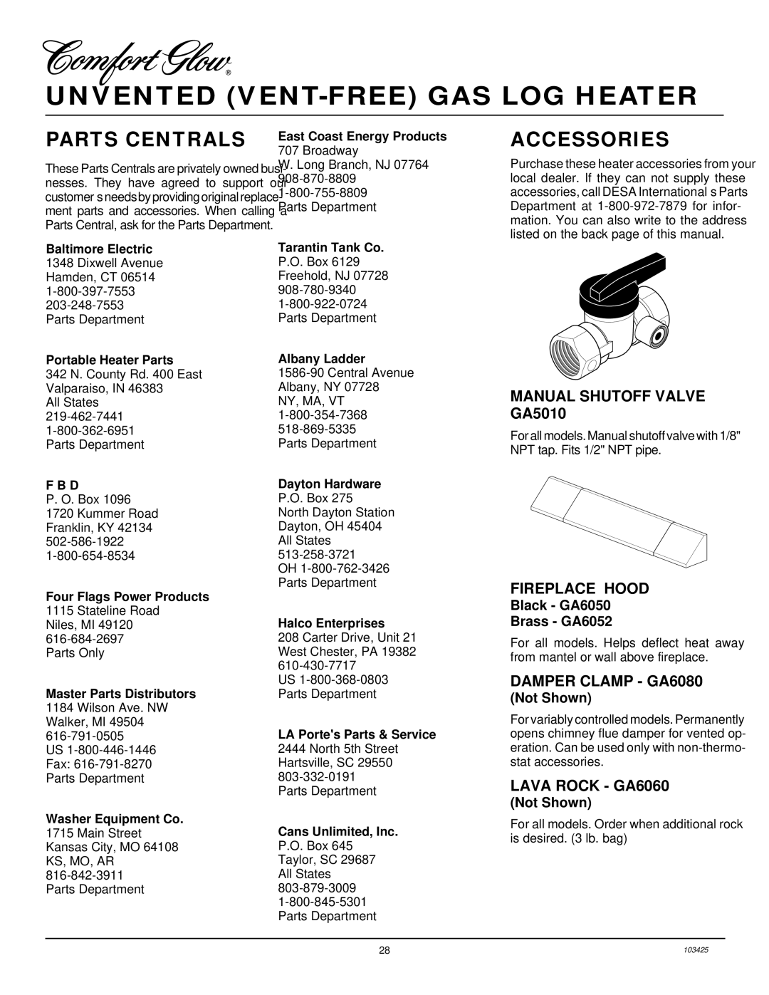
Contents OWNER’S Operation and Installation Manual What to do if YOU Smell GASSafety Information Unvented VENT-FREE GAS LOG HeaterLocal Codes Product FeaturesProduct Identification UnpackingUnusually Tight Construction AIR for Combustion and VentilationProviding Adequate Ventilation Confined and Unconfined SpaceDetermining FRESH-AIR Flow for Heater Location AIR for Combustion VentilationDetermining if You Have a Confined or Unconfined Space Building Ventilation AIRVentilation Air From Inside Ventilation Air From OutdoorsCheck GAS Type InstallationInstallation Clearances Minimum Fireplace Clearance to Combustible MaterialsIf Using Mantel Minimum Noncombustible Material ClearancesFloor Clearances Determining Minimum Mantel Clearance When Using a HoodMantel Clearances Determining Minimum Mantel ClearanceInstalling Damper Clamp Accessory for Vented Operation Installing Heater Base AssemblyInstallation Items Needed Attaching Flexible Gas Hose to Heater Gas RegulatorConnecting to GAS Supply External Regulator With Vent Pointing DownPressure Testing Heater Gas Connections Pressure Testing Gas Supply Piping SystemChecking GAS Connections Installing Logs Installing Rear LogOperating Heater For Your Safety Read Before LightingLighting Instructions To Turn OFF GAS To Appliance Manual Lighting ProcedureThermostat Control Operation Variable Control Operation Inspecting BurnersPilot Flame Pattern Front Burner Flame Pattern Cleaning and MaintenanceCleaning Burner Injector Holder and Pilot AIR Inlet Hole LogsTroubleshooting Observed Problem Possible Cause RemedyMaintenance, Gas leak. See Warning statement at Optional Positioning of Thermostat Sensing Bulb For Masonry and FACTORY-BUILT Metal FireplaceTechnical Service SpecificationsService Hints Replacement PartsIllustrated Parts Breakdown Variable Manually Controlled ModelsParts List Variable MANUALLY- Controlled ModelsThermostat Controlled Models CGG3324PT KEY Part Number Description QTYAccessories Parts Centrals103425 Warranty Information Keep this Warranty

CGG2618P, CGG3630P, CGG3324PT specifications

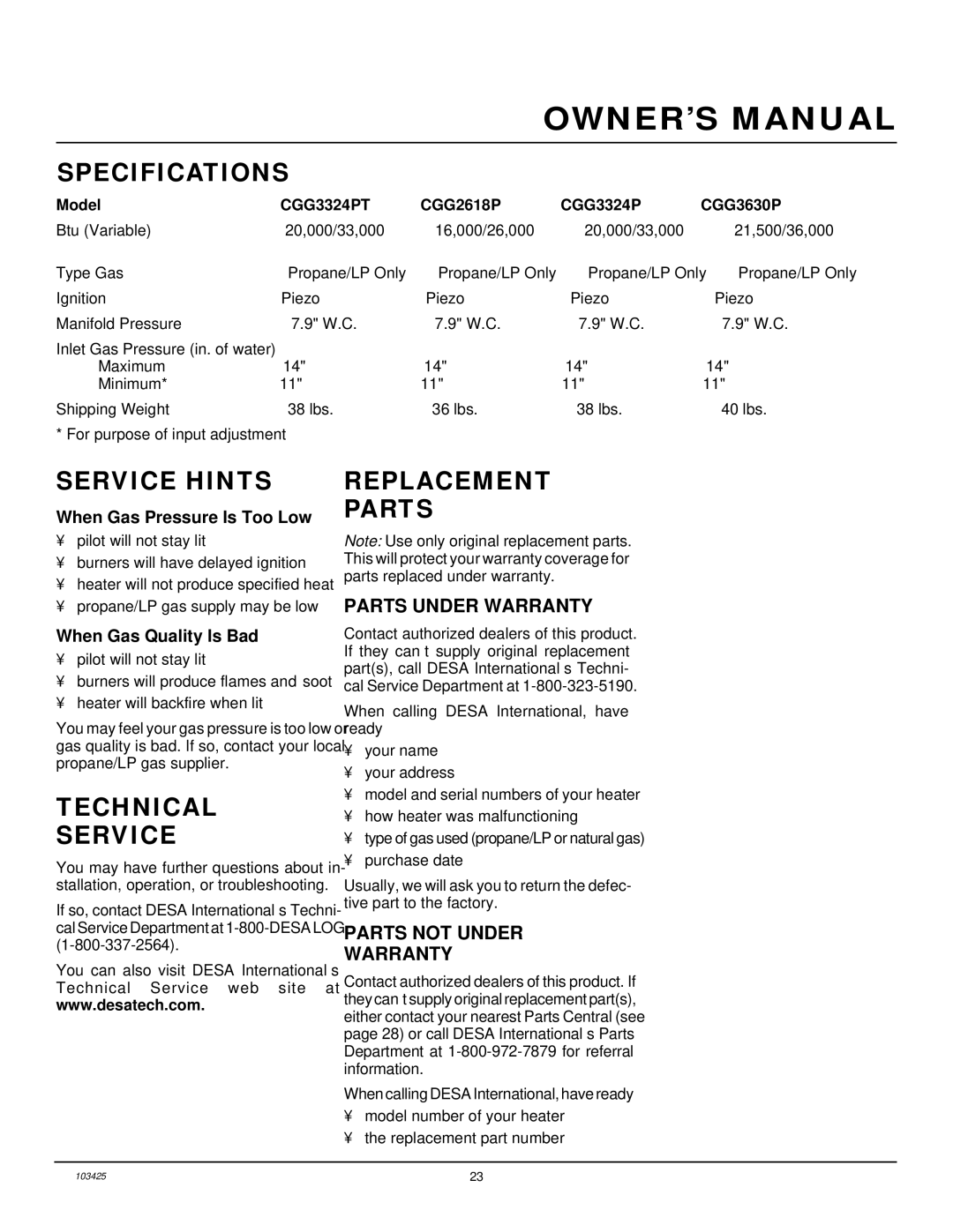
Desa Tech is a well-known name in the realm of innovative and efficient heating solutions, and its CGG2618P, CGG3630P, and CGG3324PT models exemplify the brand's commitment to excellence in design and functionality. Each of these products is tailored to meet specific heating needs while incorporating advanced technologies for improved efficiency and user experience.

The CGG2618P is a compact yet powerful gas heater designed for smaller spaces. With a maximum output of 26,000 BTUs, it can easily warm up a room quickly and efficiently. One of its standout features is the built-in thermostat, which allows users to set their desired temperature with precision, ensuring comfort without wasteful energy use. The heater also includes an electronic ignition system, offering hassle-free startup. Its sleek design and lightweight construction make it easy to move wherever heating is needed.

On the other hand, the CGG3630P boasts a larger capacity with a maximum output of 36,000 BTUs, making it ideal for larger rooms or even garages and workshops. This model features dual heat settings, allowing users to customize their heating experience based on the size of the space and the external temperature. The innovative flame sensing technology ensures that the unit operates safely by automatically shutting off the gas supply when the flame is not detected. Additionally, it is designed with a durable casing that can withstand the wear and tear of everyday use, ensuring longevity and reliability.

The CGG3324PT combines elements from both models to cater to versatile heating needs. With an output of 33,000 BTUs, it is suitable for medium to larger-sized spaces. This model is unique for its portability, equipped with wheels that make it easy to transport from room to room. It also features a piezo ignition system, which requires no external power source, enhancing its usability in power outages or remote locations. Furthermore, the CGG3324PT is designed with safety in mind, featuring an automatic shut-off function that activates in the event of overheating.

All three models from Desa Tech share a commitment to energy efficiency. Utilizing advanced combustion technologies, they minimize fuel consumption while maximizing heat output. This means not only lower energy bills but also a smaller carbon footprint. Additionally, their sleek designs add a touch of modernity to any space while providing efficient heating solutions.

In summary, Desa Tech's CGG2618P, CGG3630P, and CGG3324PT models offer a range of features and technologies that cater to diverse heating requirements. Whether it's for a small room, a workshop, or consistent indoor comfort, these models provide effective and efficient solutions while prioritizing safety and user convenience.