Heat & Glo LifeStyle
manual
Diagram of the 7000XLS and 6000XLSB
Install
Wiring the Fireplace
Maintenance
Safety
Page 6
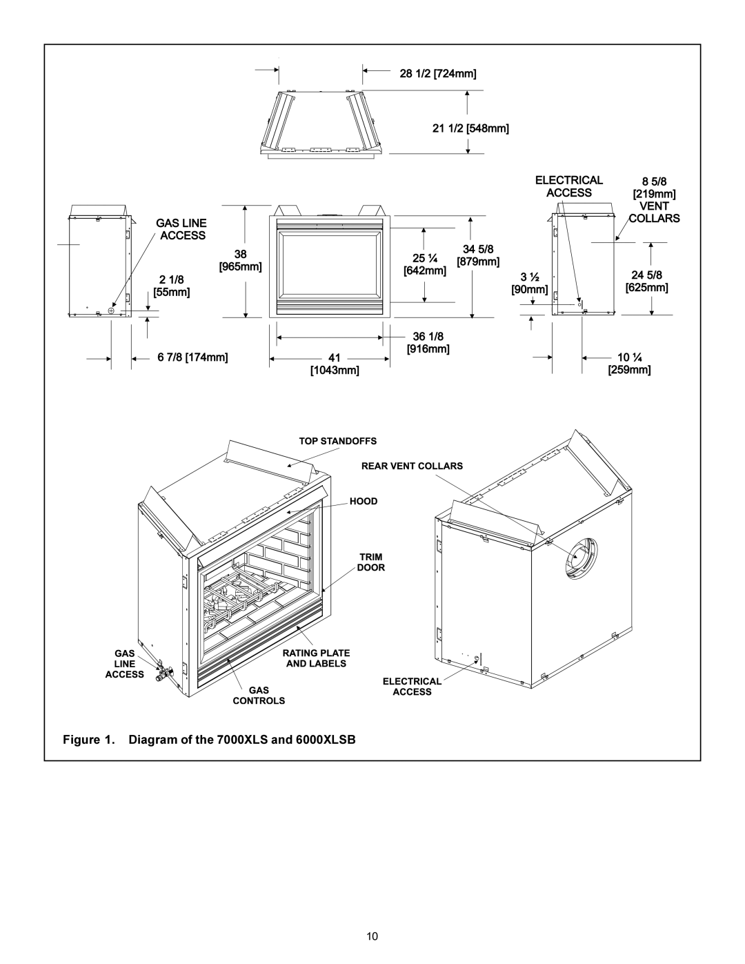
Figure 1. Diagram of the 7000XLS and 6000XLSB
10
Page 5
Page 7
Image 6
Page 5
Page 7
Contents
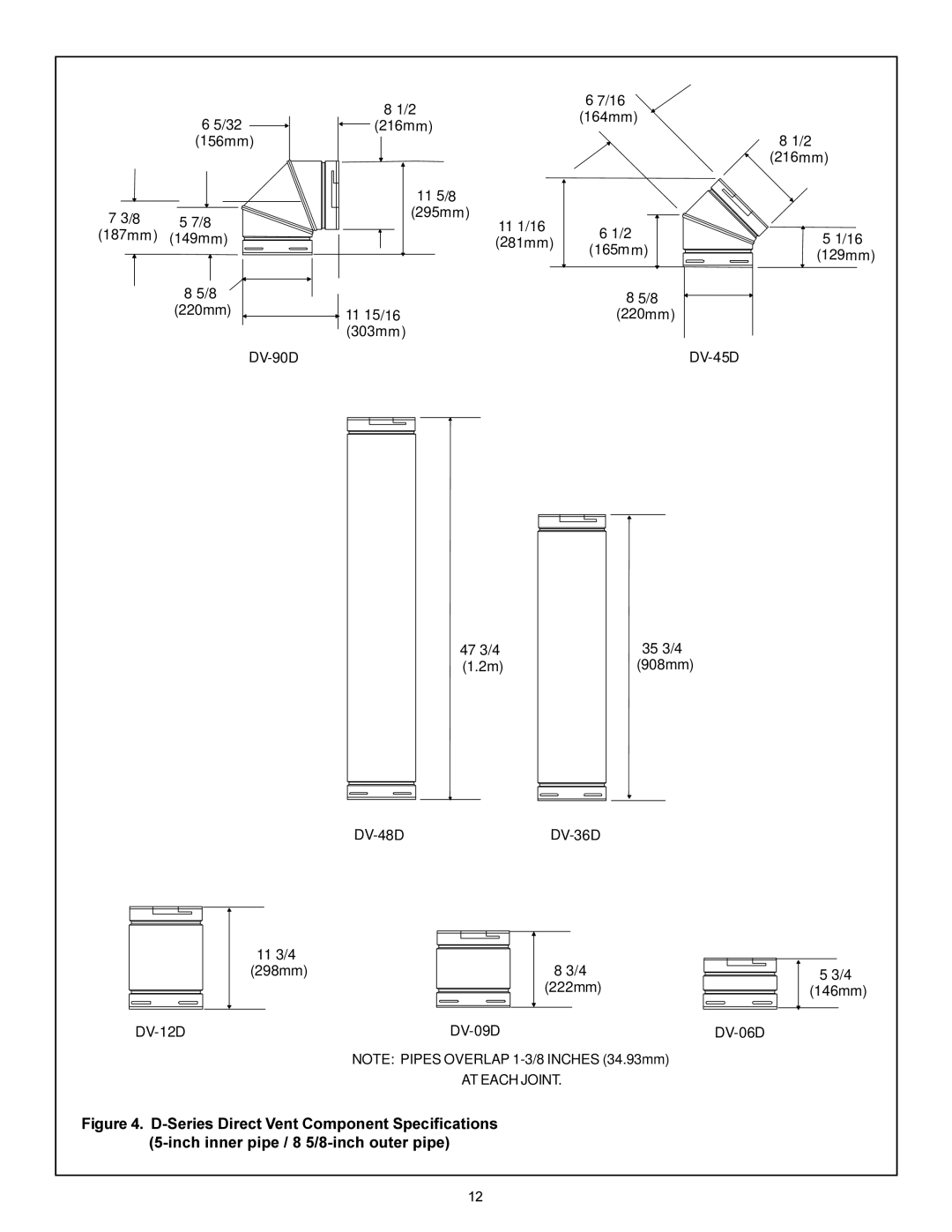
Installers Guide
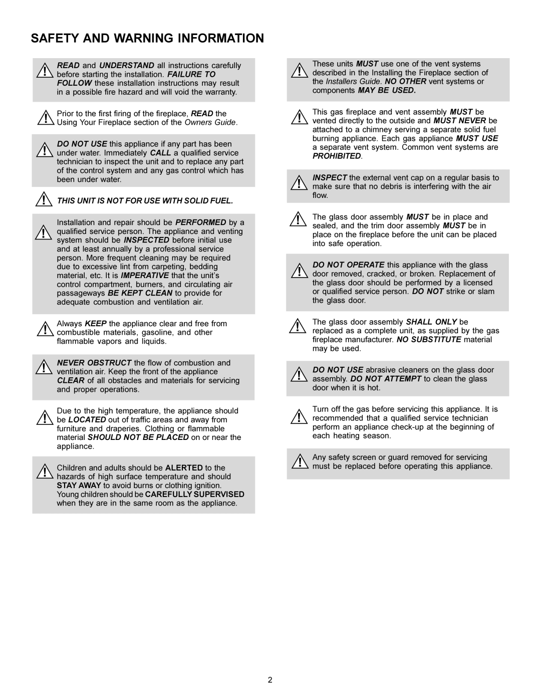
What to do if you smell gas
Safety and Warning Information
Table of Contents
Appliance Certification
High Altitude Installations
Installation Codes
Certification
Pre-install Preparation
Introducing the Heat-N-Glo Gas Fireplaces
ANY Such Action MAY Possibly Cause a Fire Hazard
Diagram of the 7000XLS and 6000XLSB
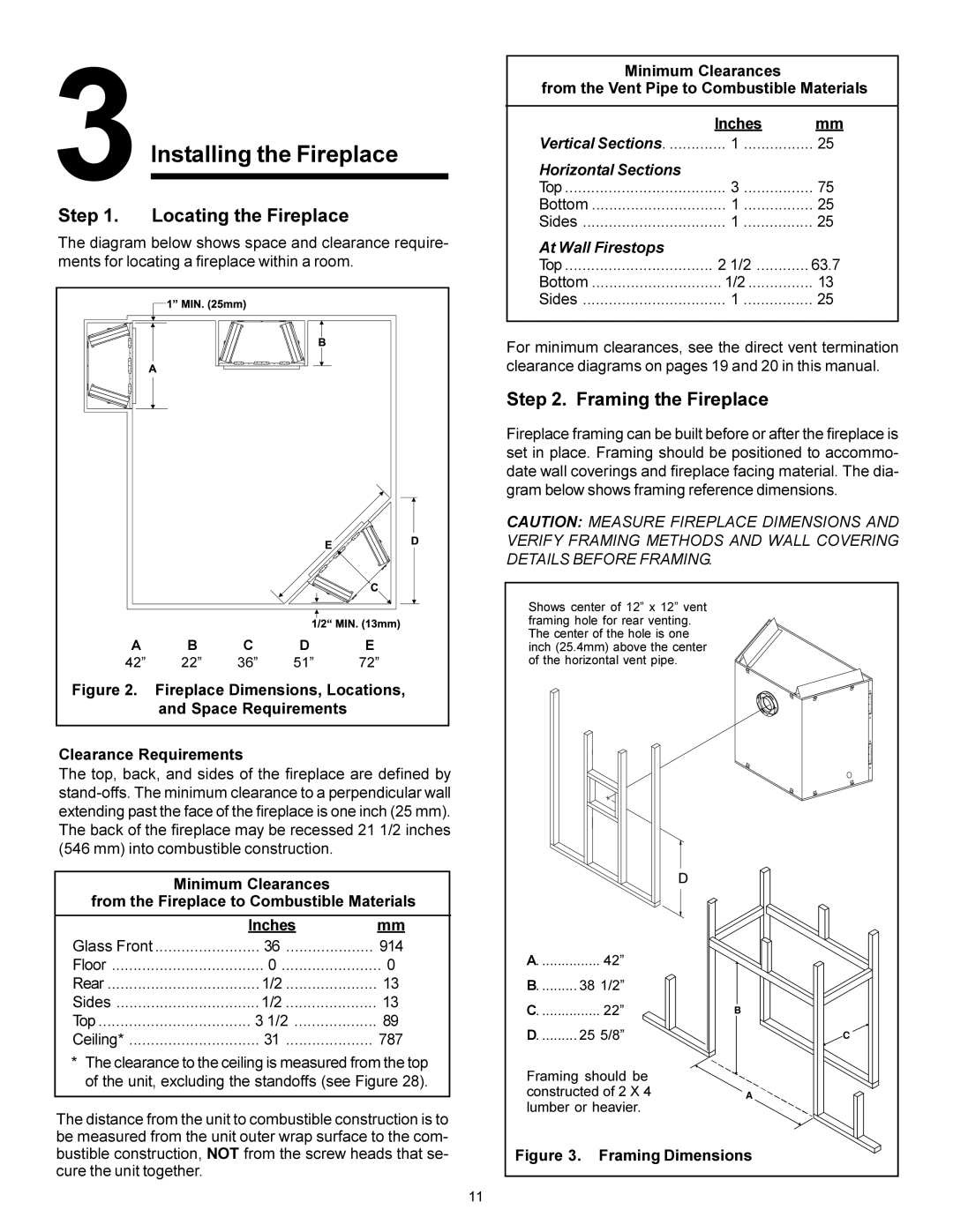
Framing the Fireplace
Fireplace Dimensions, Locations
Locating the Fireplace
Space Requirements Clearance Requirements
32 156mm
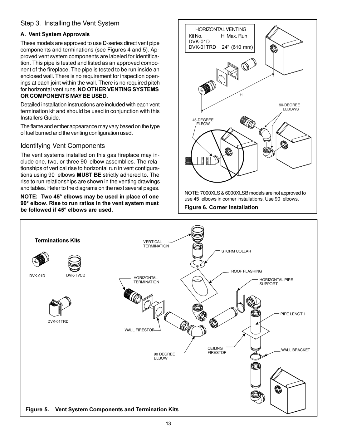
Vent System Approvals
Installing the Vent System
Identifying Vent Components
Vent System Components and Termination Kits
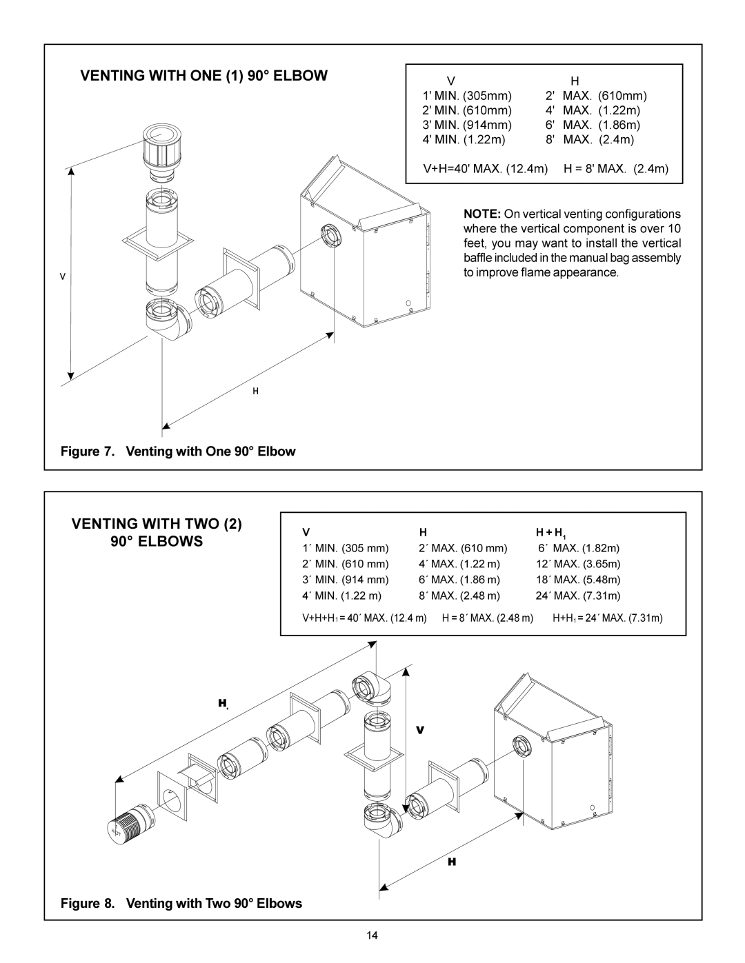
Venting with ONE 1 90 Elbow
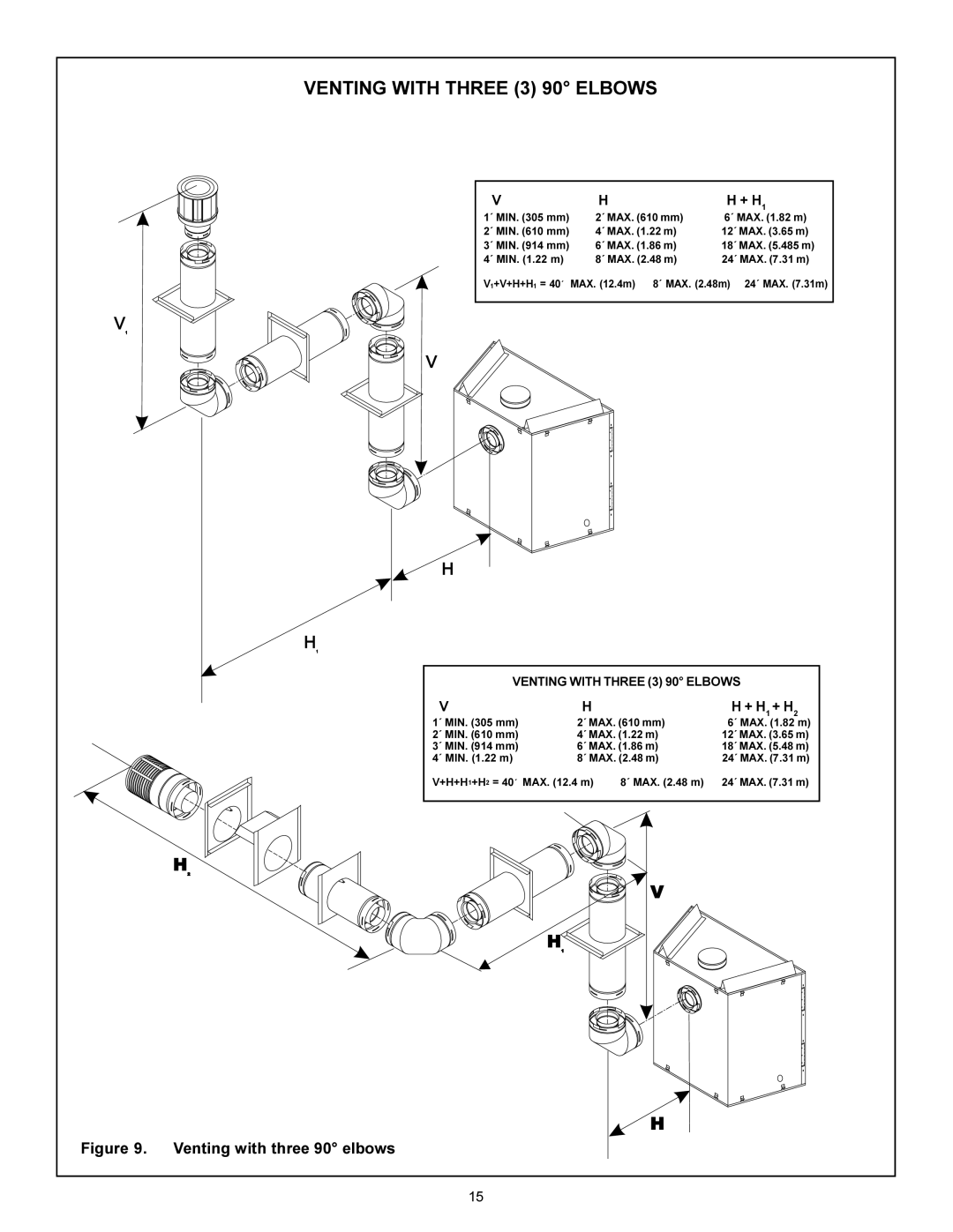
Venting with Three 3 90 Elbows
Venting with three 90 elbows
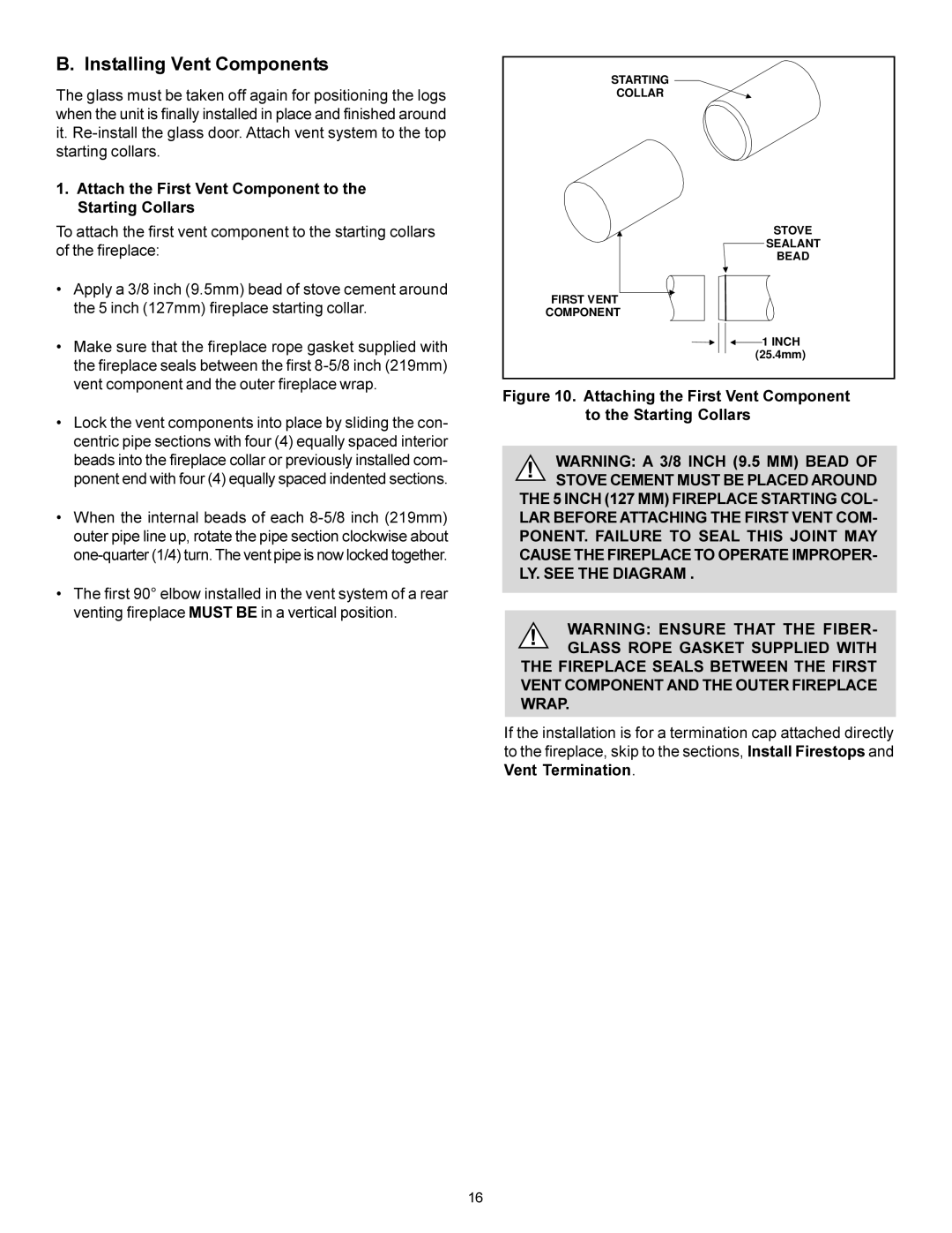
Installing Vent Components
Attach the First Vent Component to the Starting Collars
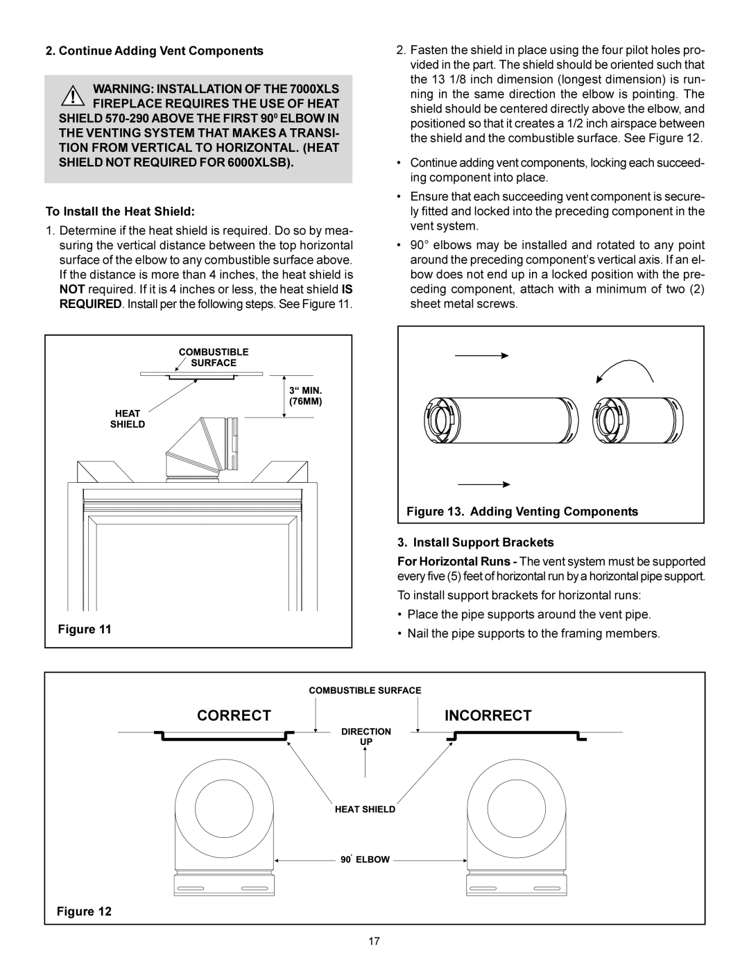
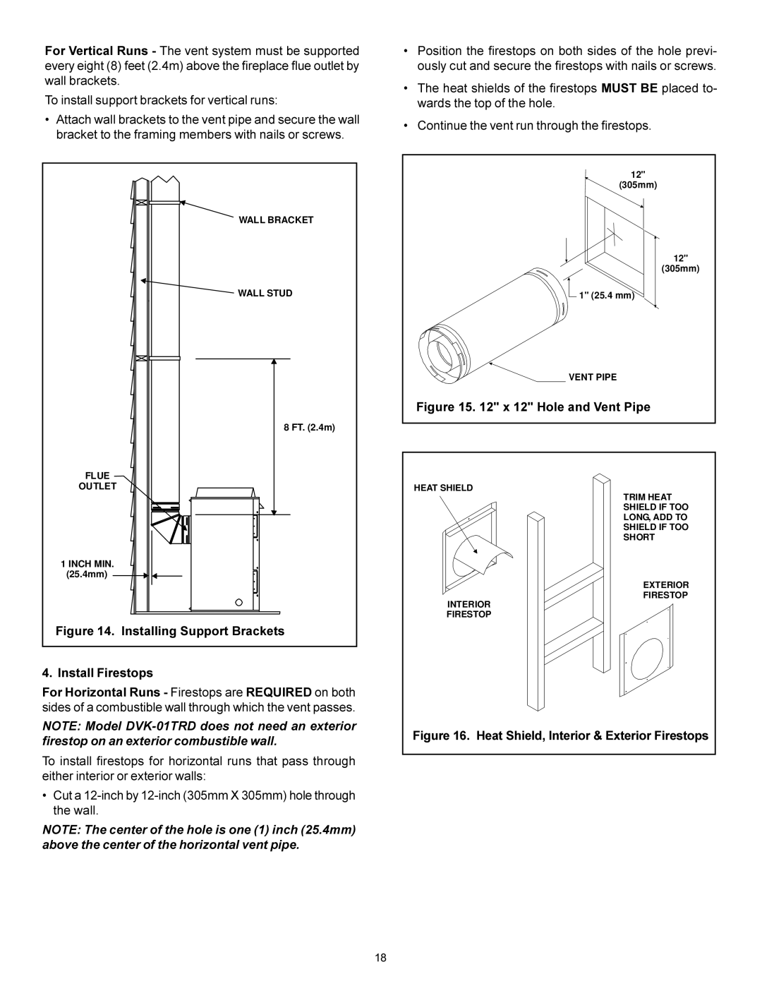
To install support brackets for horizontal runs
To Install the Heat Shield
Install Support Brackets
Continue Adding Vent Components
12 Hole and Vent Pipe
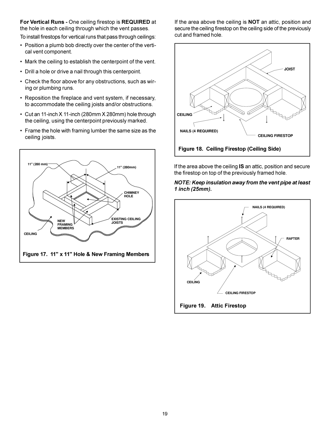
Ceiling Firestop Ceiling Side
Attic Firestop
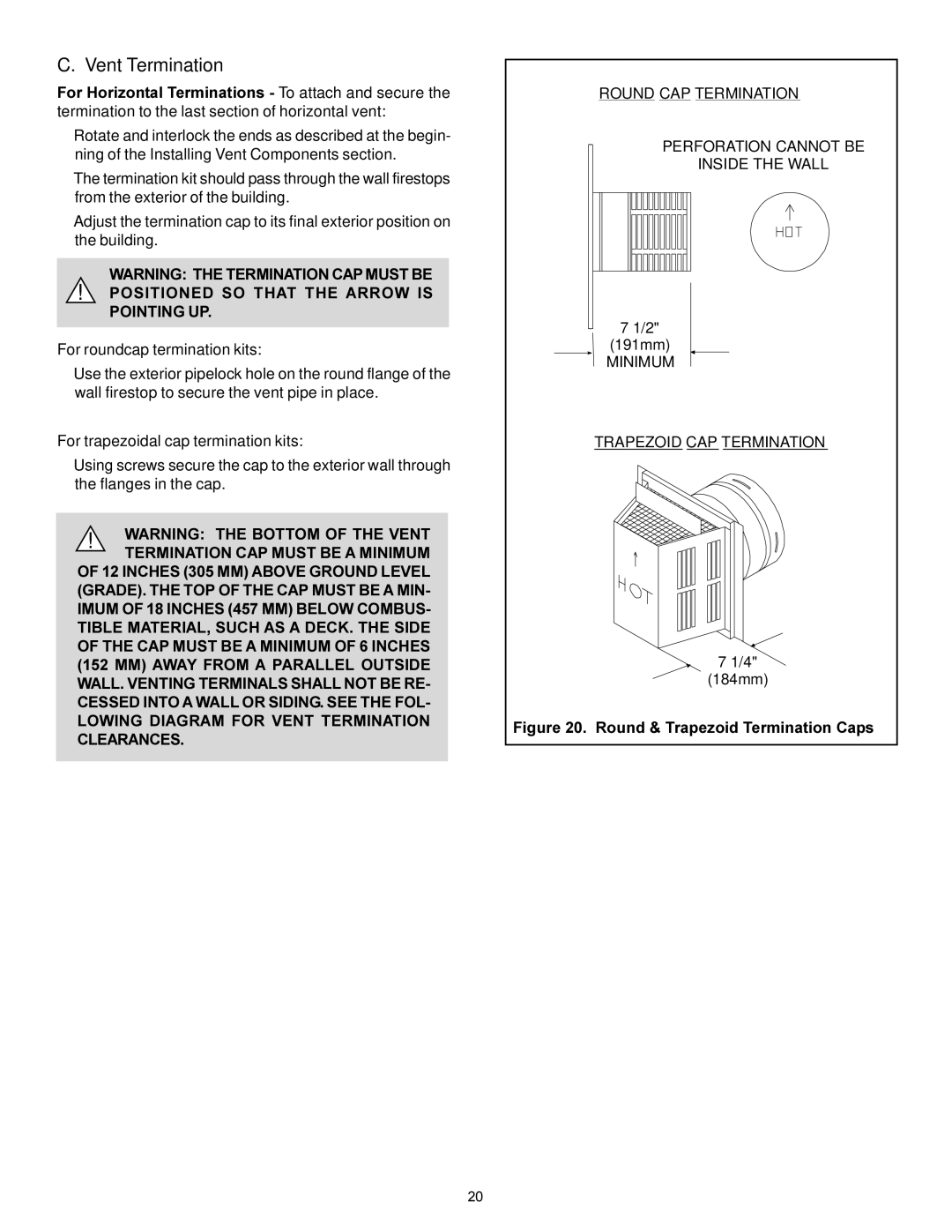
Vent Termination
Pointing UP
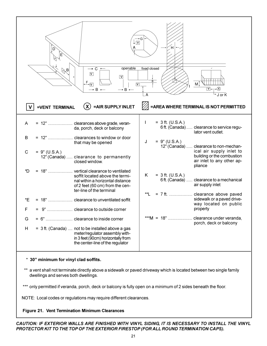
=VENT Terminal =AIR Supply Inlet
Minimum for vinyl clad soffits
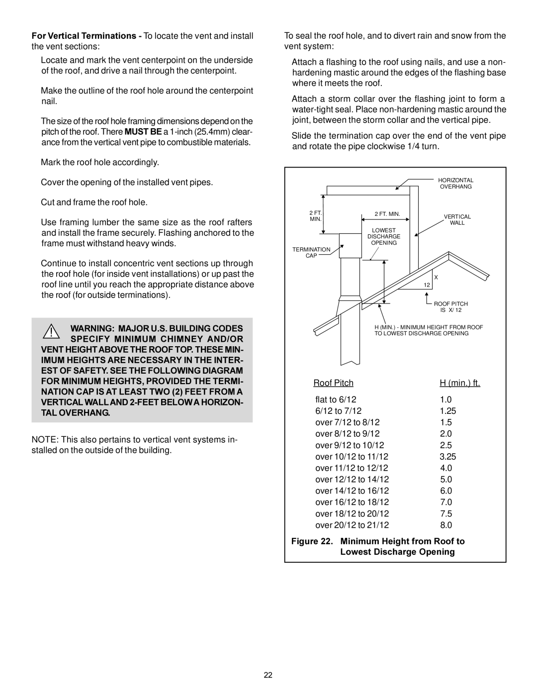
Minimum Height from Roof to Lowest Discharge Opening
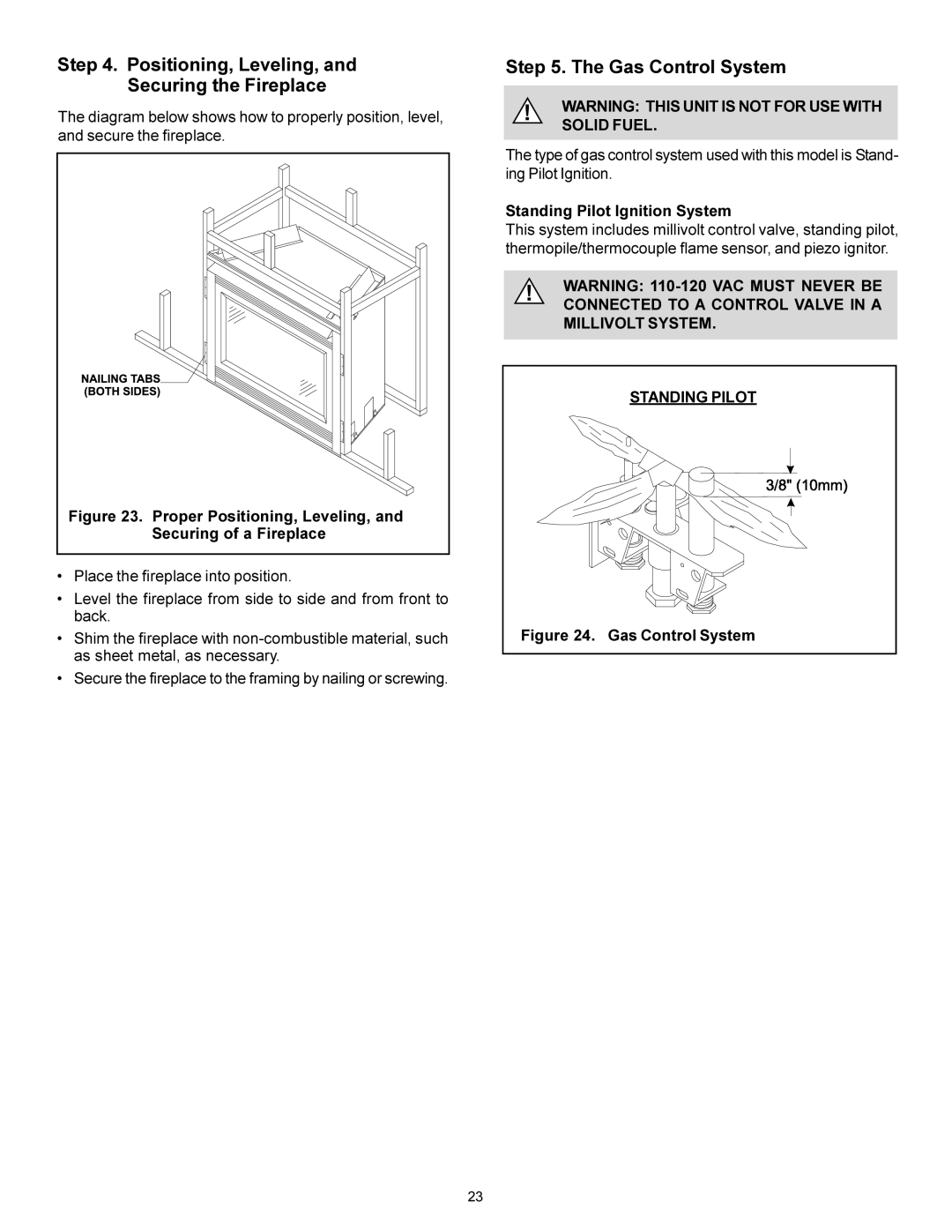
Securing of a Fireplace
Positioning, Leveling, and Securing the Fireplace
Gas Control System
Standing Pilot Ignition System
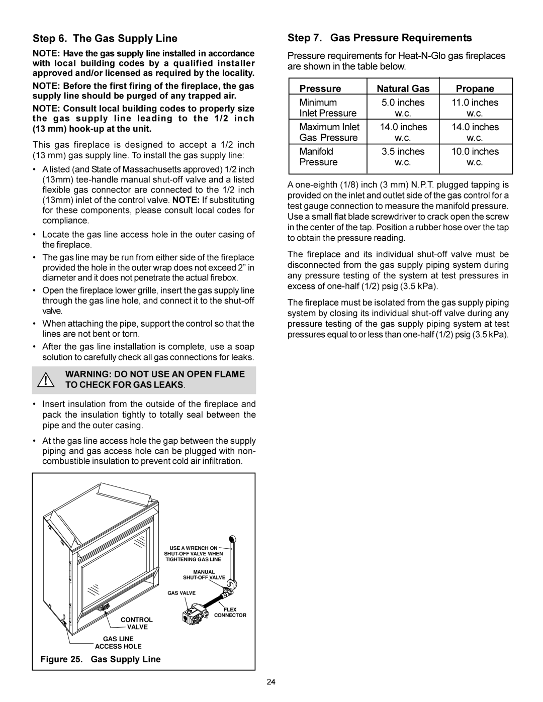
Gas Supply Line
Gas Pressure Requirements
To Check for GAS Leaks
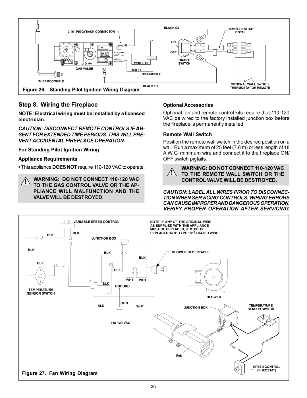
Optional Accessories
Wiring the Fireplace
For Standing Pilot Ignition Wiring Appliance Requirements
Remote Wall Switch
Finishing
Hearth Extensions
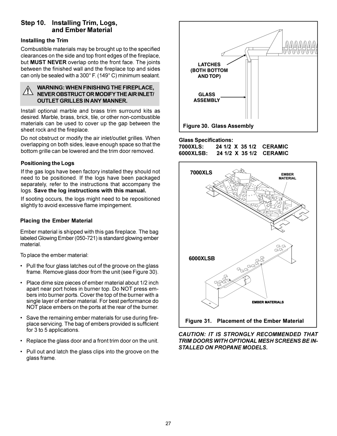
Installing Trim, Logs, and Ember Material
Ceramic
Before Lighting the Fireplace
After the Installation
Double-check for faulty components
Lighting the Fireplace
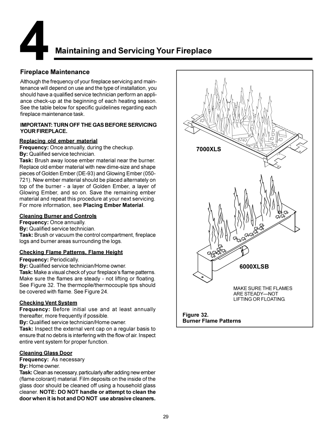
Fireplace Maintenance
Important Turn OFF the GAS Before Servicing Your Fireplace
Related pages
All Diagram page
Saving a Bindings Chart for Slick V3.3
Terminal Diagram for Emerson N1652
Set up the chart guard zone for NorthStar Navigation 8000I
Wiring Diagram for Electrolux E24CM75GSSA
Flowchart 2.16-Nonfunctioning Device for HP nx7000
Connection Diagram Fig for Pioneer DEH-P4770MP
Block Diagram Display Section for Sony CDX-GT260S
Schematic Diagrams for Fluke 5720A
Feature Chart for Panasonic MC-GG213
Grilling Chart for Tricity Bendix SIE533
What maintenance tips are available for the
Flymo Pac a Shredder
?
Top
Page
Image
Contents