Enviro C-10365, EG40 DV owner manual Table of Contents

Page 3

Table of Contents

Safety Precautions

2

Table of Contents

3

Codes And Approvals

4

Specifications

5

Dimensions

5

Clearances to Combustibles

5

Preparation For Installation:

5

Initial Installation

6

Vent Termination Restrictions

6

Vent Configurations

7

Vent Restrictor Ring

7

Vent Parts

8

Planning Your Installation

9

Horizontal Installation

10

Corner Installations

12

Vertical Installation

12

Cathedral Ceiling Installation

15

Freestanding Direct Vent Kit With Coupler

15

Venting into a Class ‘A’ Chimney

18

Mobile Home Installation

18

Electrical Requirements

19

Replacing The Blower

20

Adjusting The Venturies

20

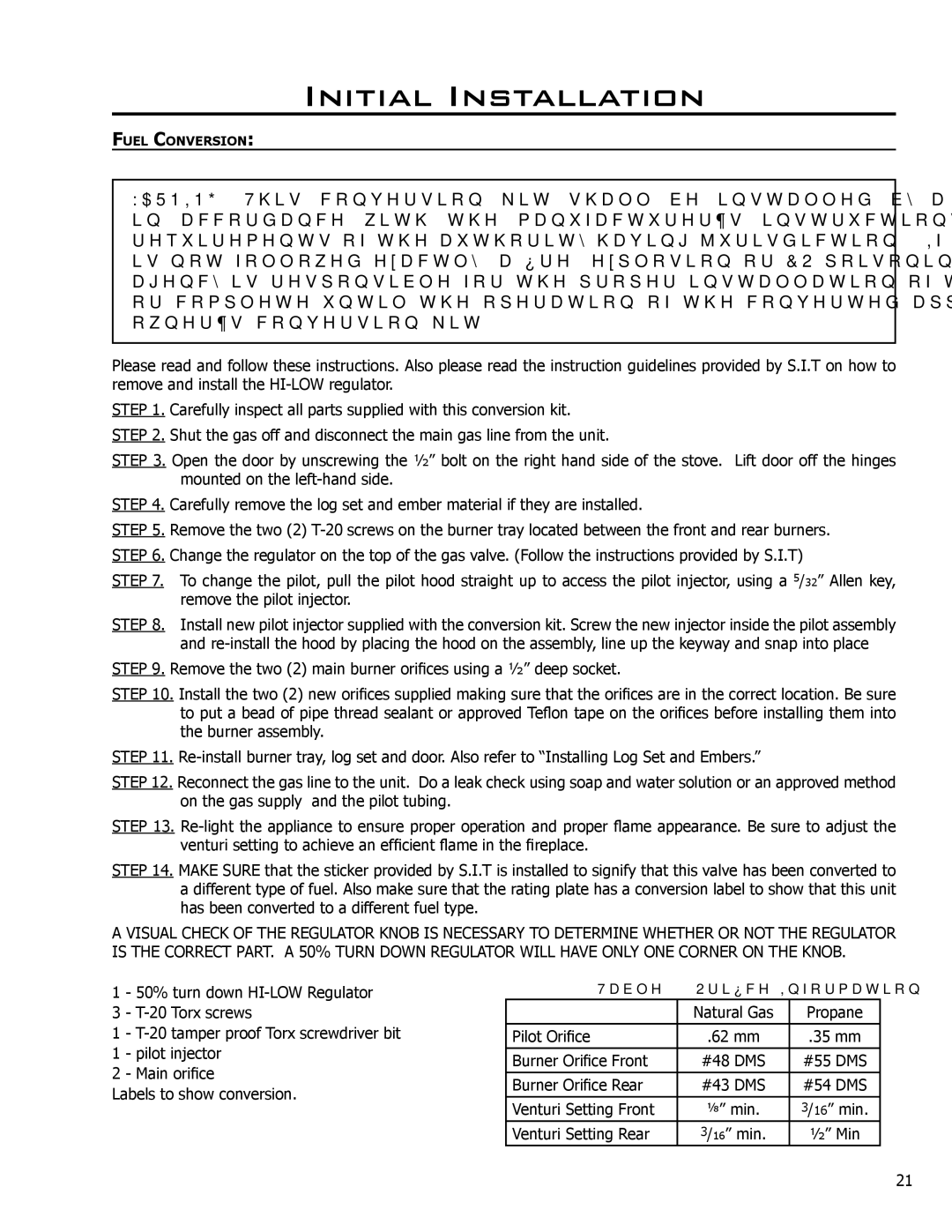
Fuel Conversion

21

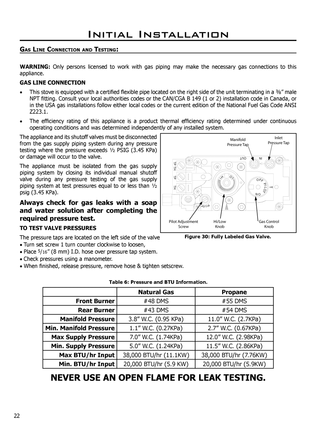
Gas Line Connection and Testing

22

Secondary Installation

23

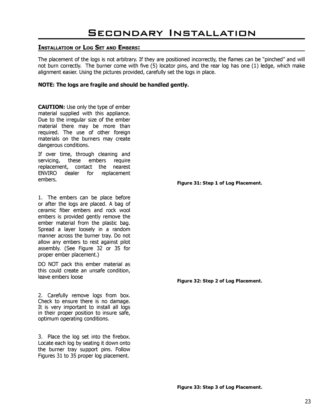
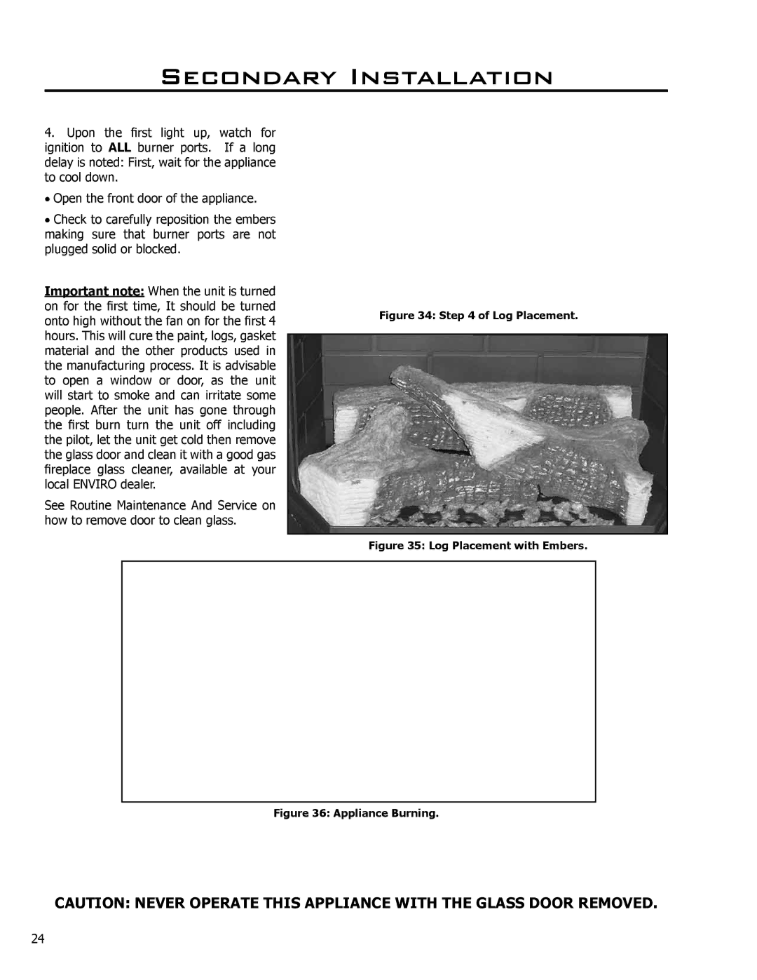
Installation of Log Set and Embers

23

Operating Instructions

25

Lighting Instructions

25

Turning Gas Off To Appliance

25

Routine Maintenance and Service

26

Trouble Shooting

27

Parts List

28

Parts Diagram - Chassis

30

Parts Diagram - Gas Tray & Door

31

Warranty

32

Installation Data Sheet

33

3

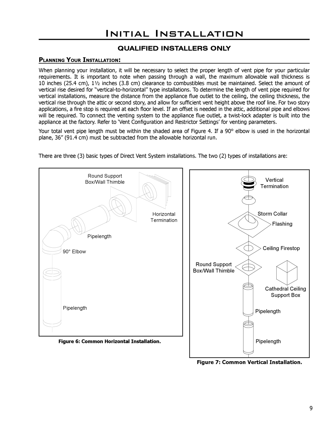
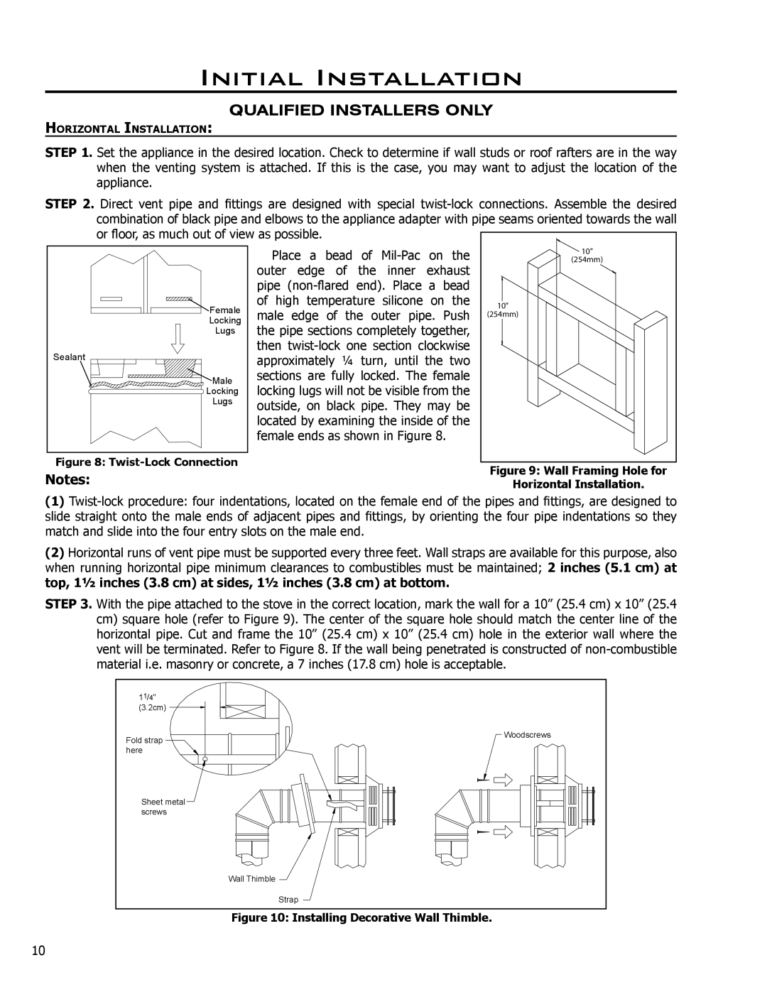
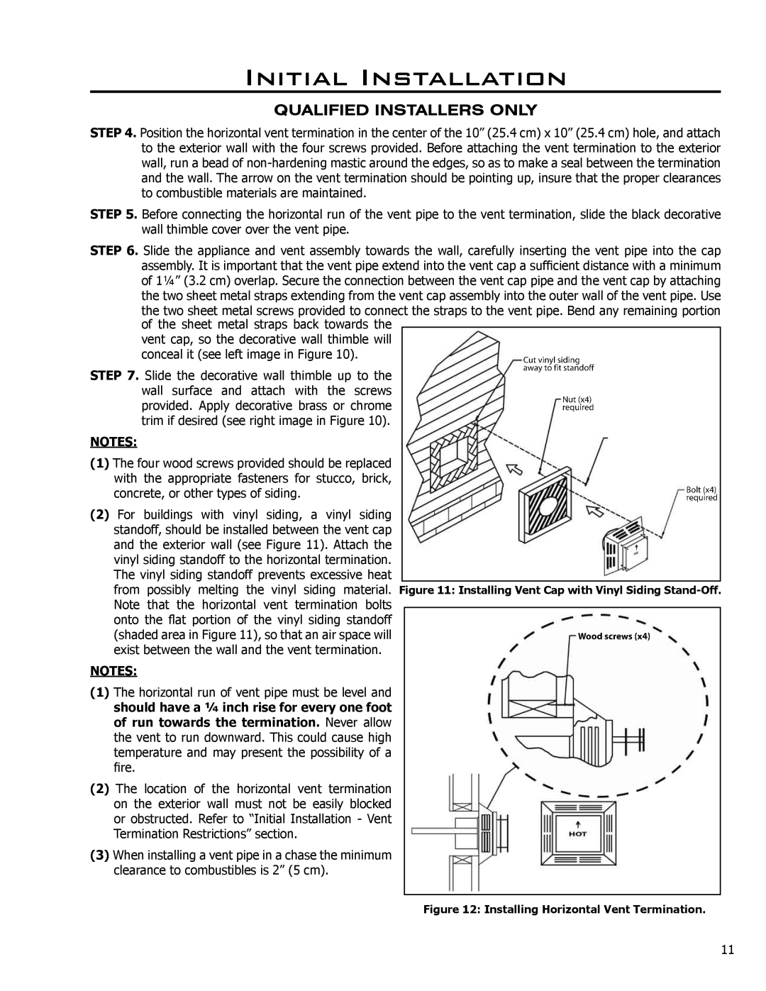
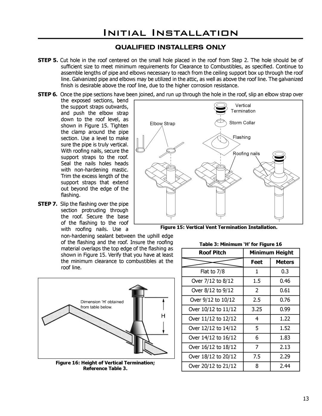
Image 3
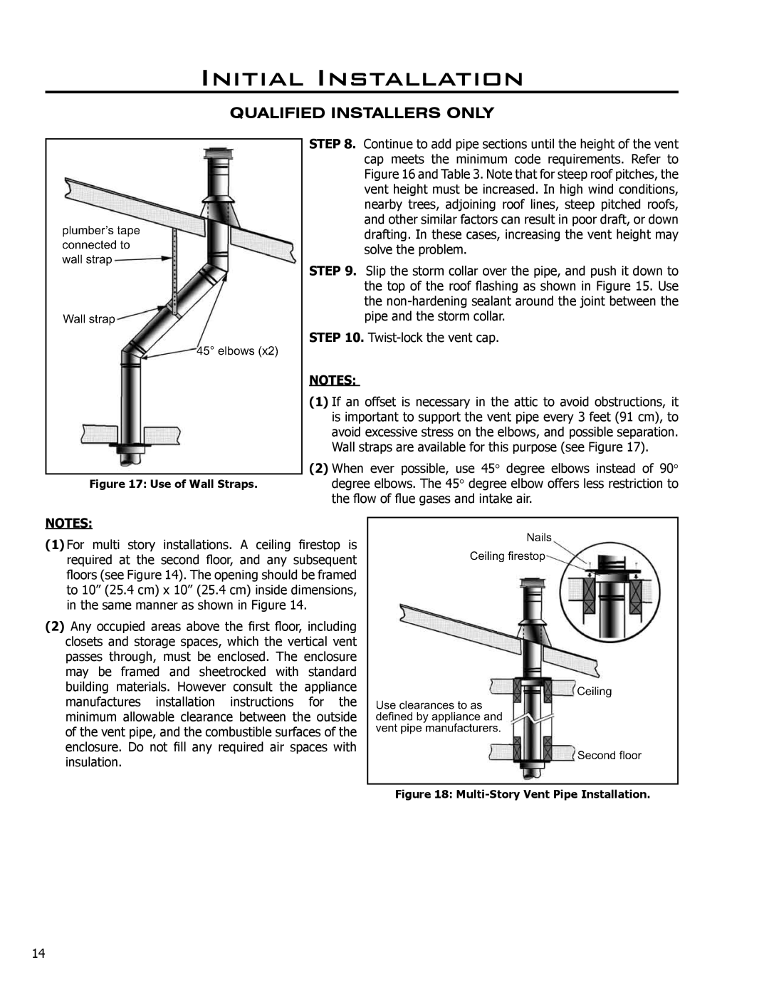
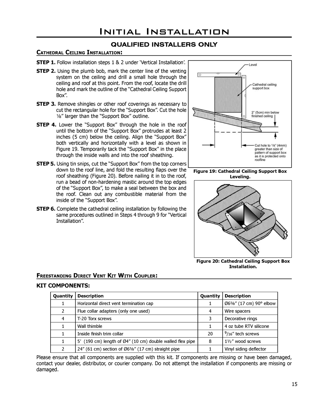
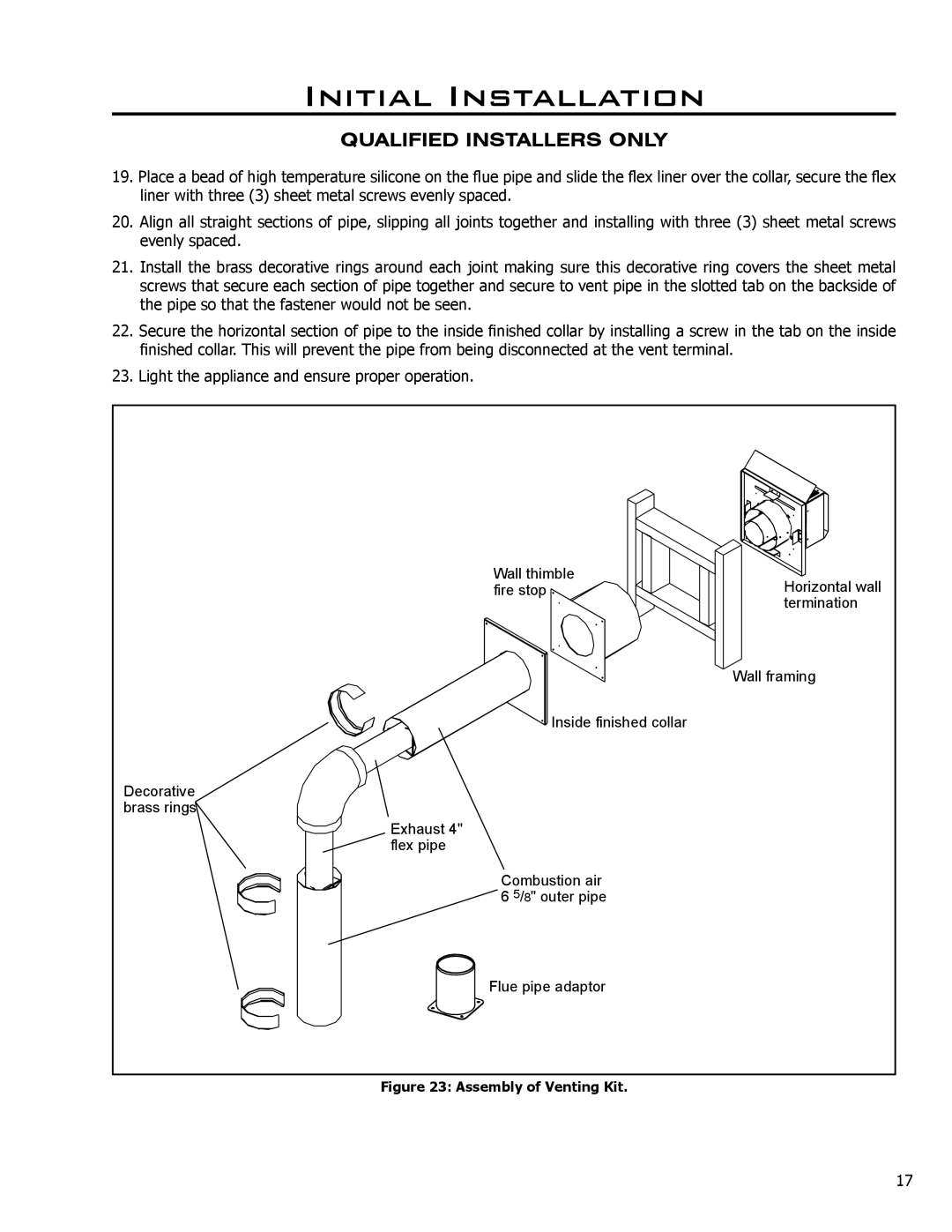
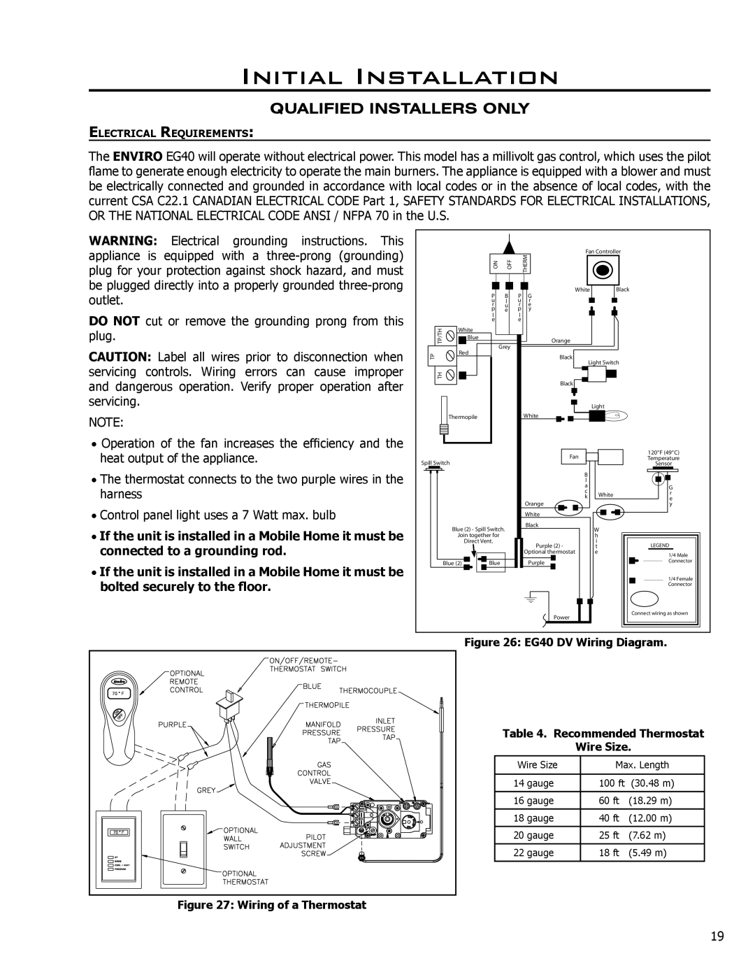
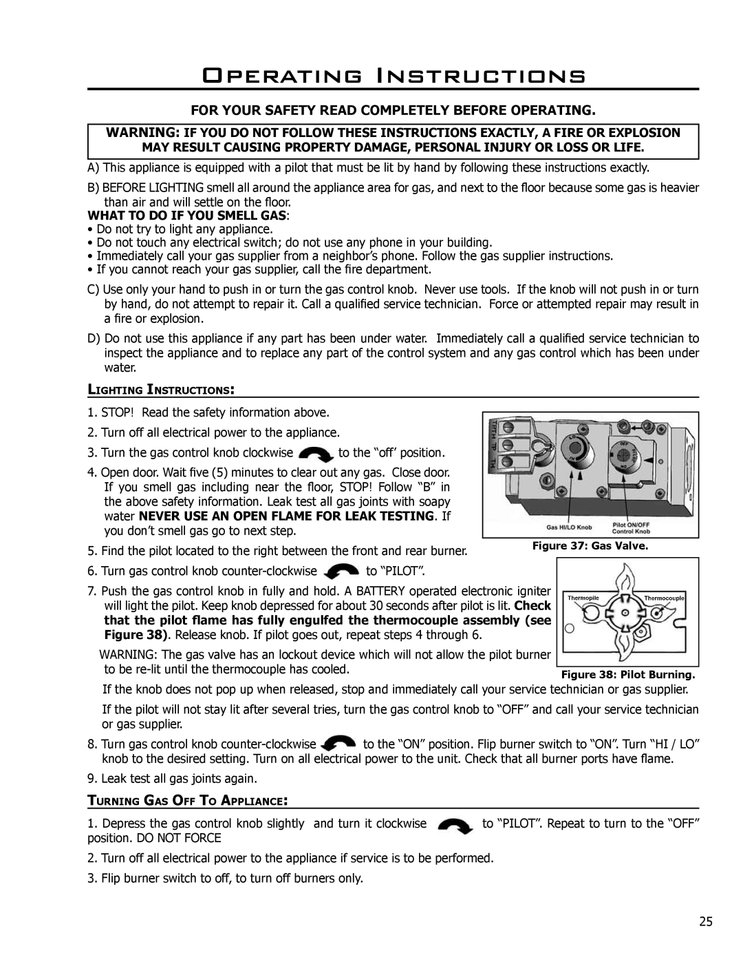
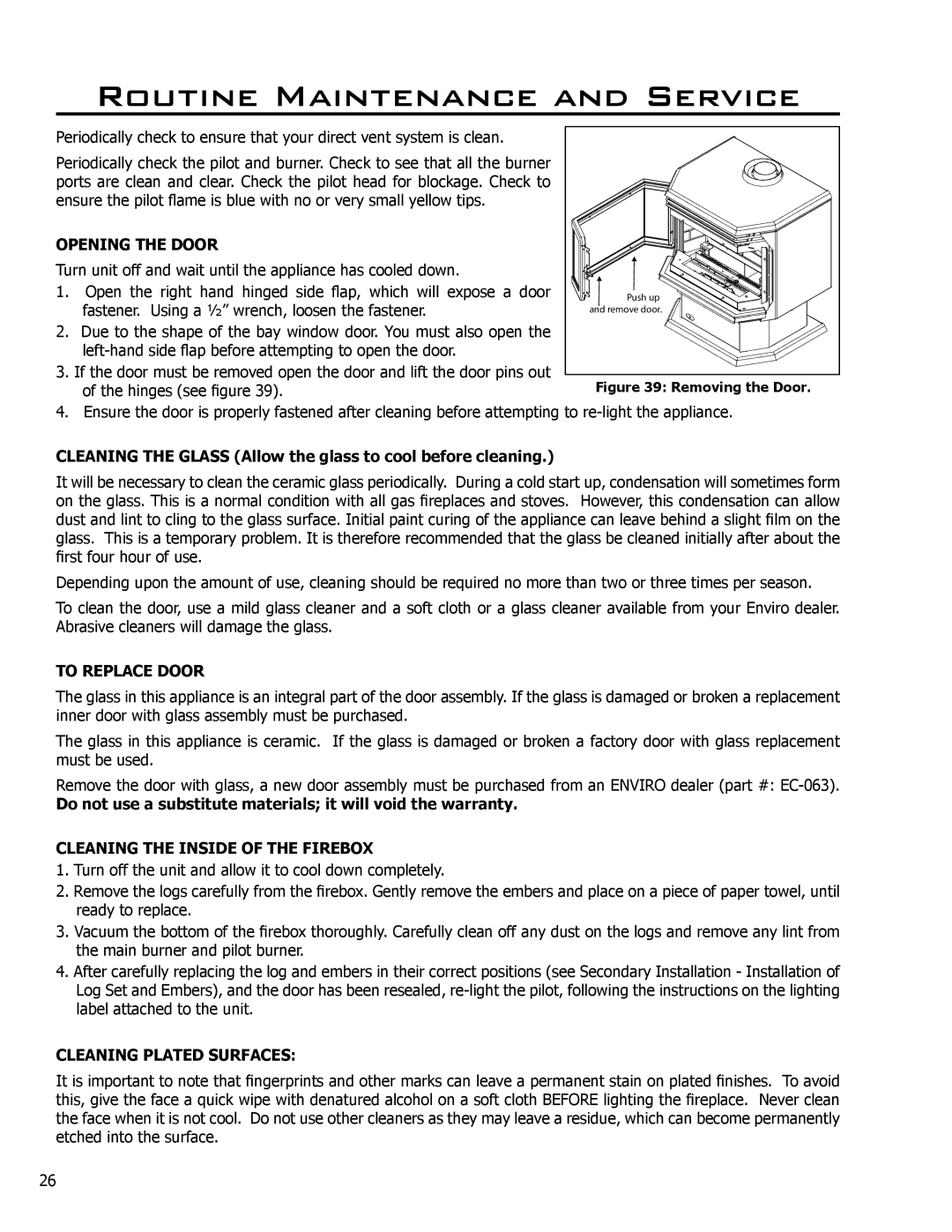
Contents S H E R W O O D I N D U S T R I E S L T D EG40 DVSafety Precautions For Your SafetyGeneral Table of Contents Codes And Approvals Vented GAS Fireplace Heater EG40 DV NG/LPGThis Enviro EG40 DV Fireplace EG40 Exterior Dimensions SpecificationsQualified Installers only Initial InstallationVent restrictor ring Vent Pipe Types with Part Numbers Venting Terminals Cannot be Recessed Into a Wall or SidingCommon Vertical Installation High temperature Silicone Male Edge Outer pipe. Push Installing Horizontal Vent Termination Do not interfere with the structural integrity of the walls Feet Meters Roof Pitch Minimum HeightMulti-Story Vent Pipe Installation KIT Components Cut away of spacers on Flex Pipe Installation InstructionsAssembly of Venting Kit Assembly of Venting into a Class ‘A’ Chimney Wiring of a Thermostat Turn the unit off and remove the log set 50% turn down HI-LOW Regulator GAS Line Connection To Test Valve PressuresPressure taps are located on the left side of the valve Log Placement Secondary InstallationLog Placement with Embers Water Never USE AN Open Flame for Leak TESTING. If Operating InstructionsWhat to do if YOU Smell GAS Opening the Door Routine Maintenance and ServiceCleaning the Inside of the Firebox Cleaning Plated SurfacesProblem Possible Cause Solution Trouble ShootingParts List Parts List Parts Diagram Chassis Parts Diagram Gas Tray & Door To the Distributor WarrantyInstallation Data Sheet