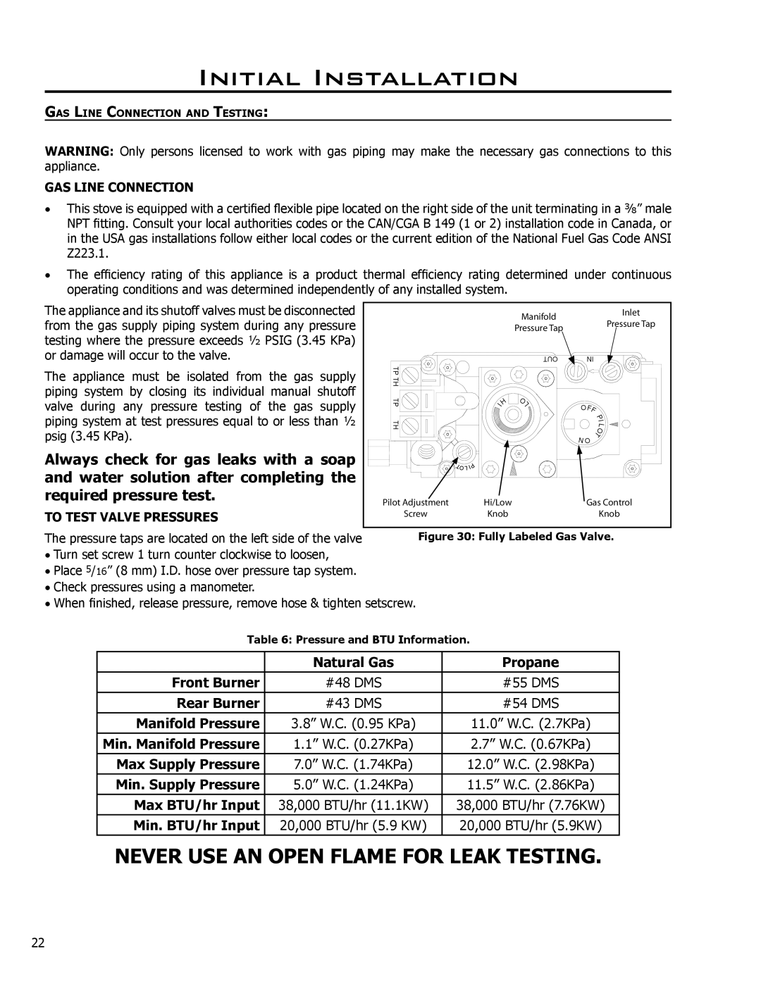
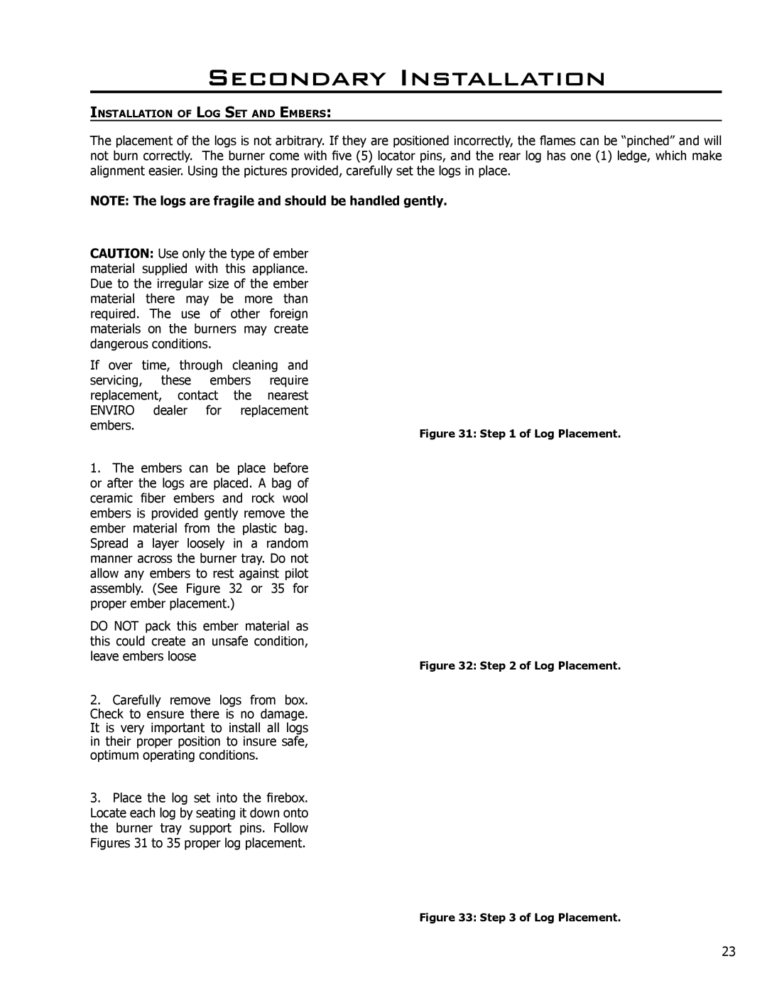
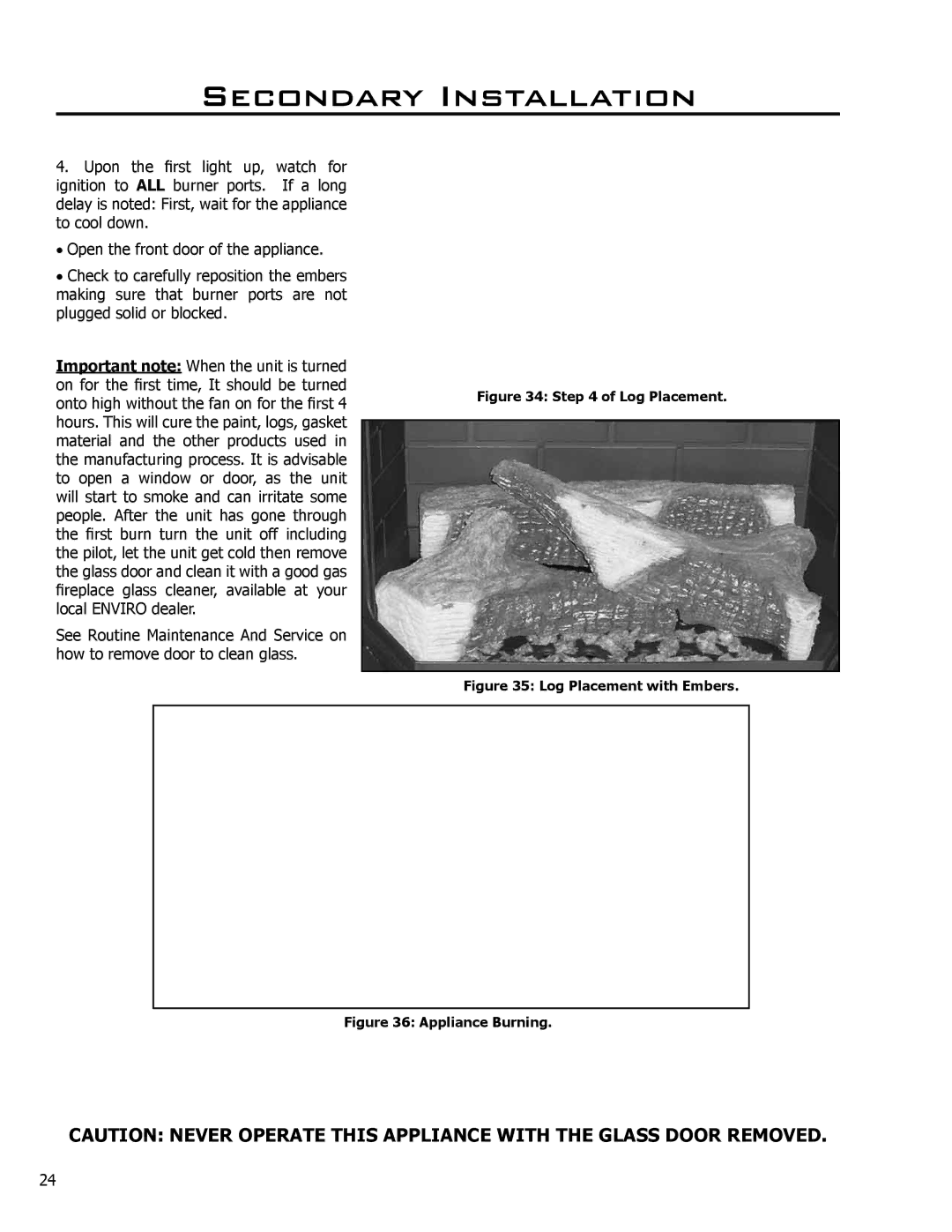
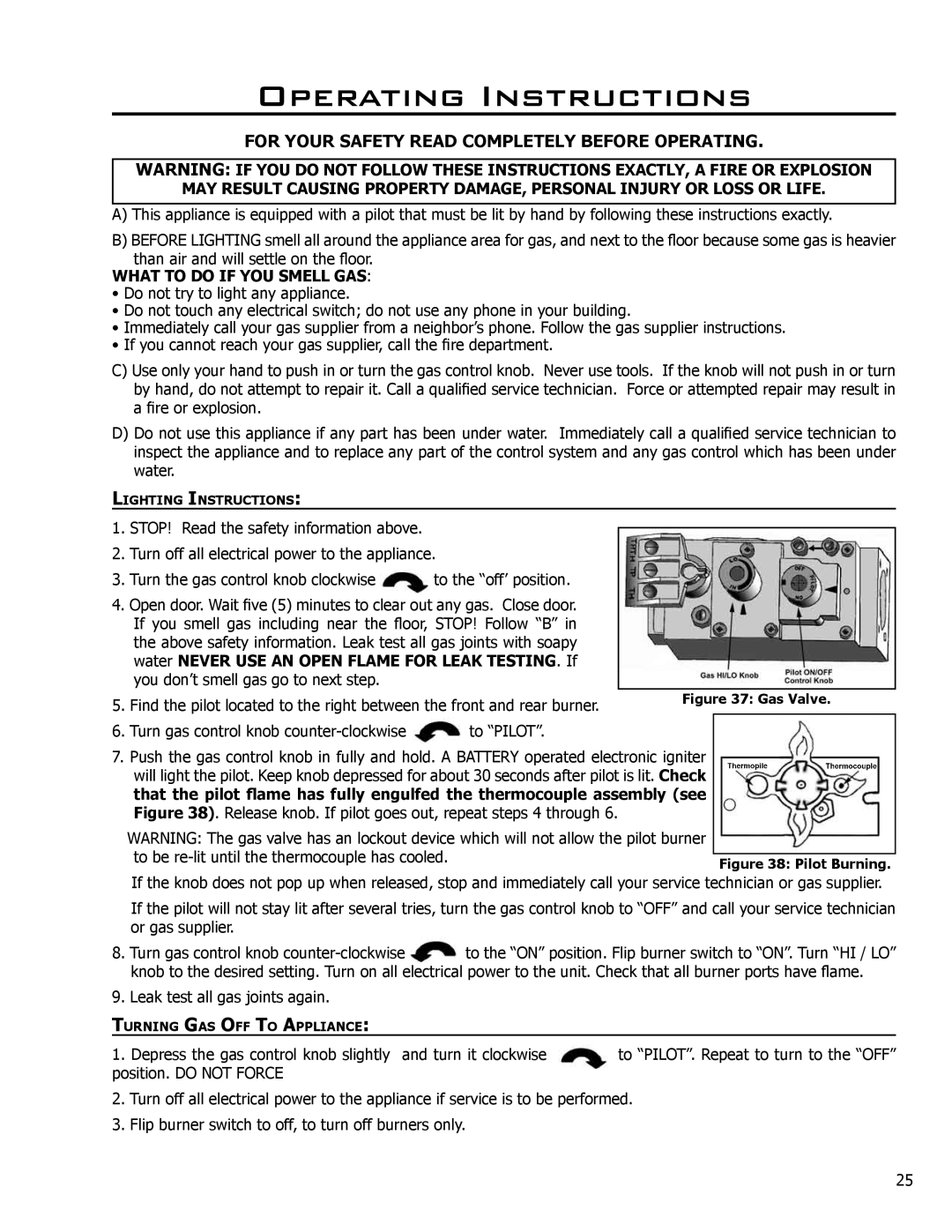
Enviro C-10365, EG40 DV owner manual Parts List

Page 29

Parts List

Reference

Part Description

Part Number

Number


Fan Access Cover Gasket

EG40-066


DV Owner’s Manual

EG40-070

13

Pedestal

EG40-080

14

Side Panel

EG40-086

15

DV Stove Top

EG40-087A


Firebox Baffle

EG40-088


Stove Top Baffle DV

EG40-091A


Venturi Cover Plate

EG40-097

16

Front Venturi

EG40-098

17

Bar Set - Painted (3 pieces)

EG40-114

17

Bar Set - Gold (3 pieces)

EG40-115

17

Bar Set - Nickel (3 pieces)

50-478


Burner Gasket

EG40-120


Steel Brick Liner

EG40-129


Brick Liner Backing

EG40-130

18

Pedestal Door

EG40-135


LP to NG Conversion Kit

EG40-200


NG to LP Conversion Kit

EG40-202

19

Ash Sill

EG40-213

20

Door Hinge (Set of 2)

EG40-302

21

Fan Mount

EG40-304

22

Pedestal Box Cover

EG40-307

23

Burner Control Assembly NG

30-014

23

Burner Control Assembly LP

30-015

24

Front Pan Burner

30-016

25

Rear Burner with Venturi

30-017


Pilot 1/8” Tube with Ferules

30-043


Log Set Complete

50-081

26

Blank Orifice #73

50-343

27

Door Cover - Gold

50-480

27

Door Cover - Painted

50-776

27

Door Cover - Brushed Nickel

50-1063

28

Convection Blower - 115V

50-514


16” Ignitor Wire

50-652


IEC Power Cord Inlet Socket

50-713


Burner Tray Top NG & LP

50-774


Vent Termination Kit

50-950

29

Image 29
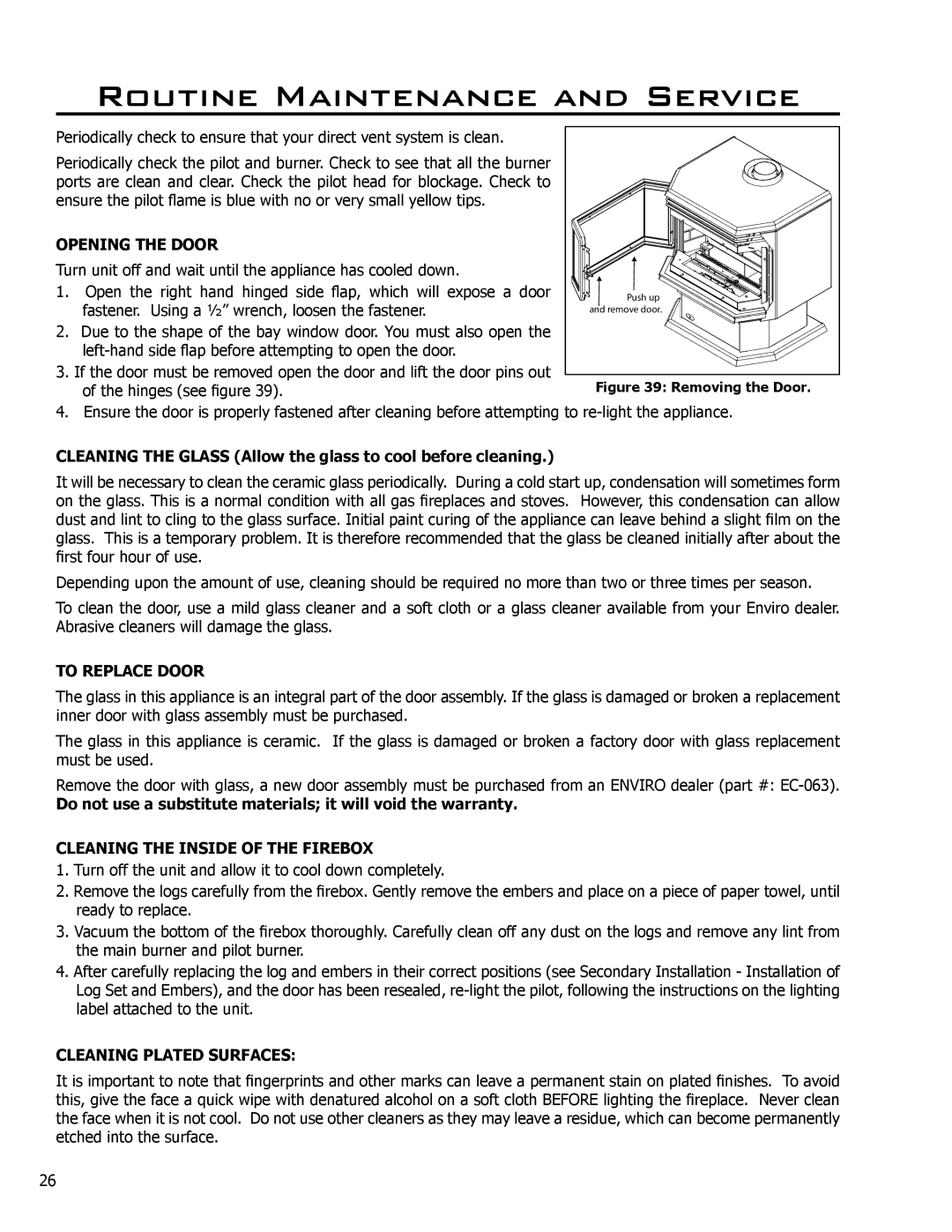
Contents S H E R W O O D I N D U S T R I E S L T D EG40 DVGeneral Safety PrecautionsFor Your Safety Table of Contents This Enviro EG40 DV Fireplace Codes And ApprovalsVented GAS Fireplace Heater EG40 DV NG/LPG EG40 Exterior Dimensions SpecificationsQualified Installers only Initial InstallationVent restrictor ring Vent Pipe Types with Part Numbers Venting Terminals Cannot be Recessed Into a Wall or SidingCommon Vertical Installation High temperature Silicone Male Edge Outer pipe. Push Installing Horizontal Vent Termination Do not interfere with the structural integrity of the walls Feet Meters Roof Pitch Minimum HeightMulti-Story Vent Pipe Installation KIT Components Cut away of spacers on Flex Pipe Installation InstructionsAssembly of Venting Kit Assembly of Venting into a Class ‘A’ Chimney Wiring of a Thermostat Turn the unit off and remove the log set 50% turn down HI-LOW Regulator Pressure taps are located on the left side of the valve GAS Line ConnectionTo Test Valve Pressures Log Placement Secondary InstallationLog Placement with Embers What to do if YOU Smell GAS Water Never USE AN Open Flame for Leak TESTING. IfOperating Instructions Cleaning the Inside of the Firebox Routine Maintenance and ServiceCleaning Plated Surfaces Opening the DoorProblem Possible Cause Solution Trouble ShootingParts List Parts List Parts Diagram Chassis Parts Diagram Gas Tray & Door To the Distributor WarrantyInstallation Data Sheet