Harman-Kardon AVR 3550HD Connecting Source Devices to the AVR, Speaker Connections, Subwoofer

Page 18

CONNECTIONS

There are different types of audio and video connections used to connect the receiver, the speakers, the video display, and the source devices. The Consumer Electronics Association has established the CEA® color-coding standard. See Table 1.

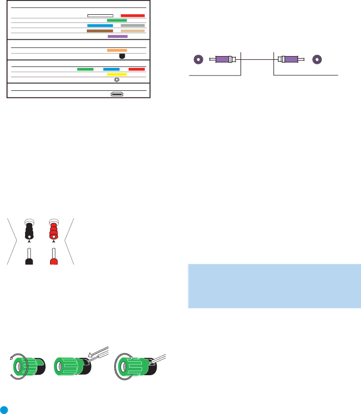
Table 1 – Connection Color Guide

Audio Connections

LeftRight

Front (FL/FR)

Center (C)

Surround (SL/SR)

Surround Back (SBL/SBR)

Subwoofer (SUB)

Digital Audio Connections

Coaxial

OpticalInput

Video Connections

Component

Y

Pb

Pr

Composite


S-Video


HDMIConnections (digital audio/video)

HDMI

Speaker Connections

Speaker cables carry an amplified signal from the receiver’s speaker terminals to each loudspeaker. They contain two wire conductors, or leads, inside plastic insulation, that are differentiated in some way, such as with colors or stripes.

The differentiation preserves polarity, without which low-frequency performance can suffer. Each speaker is connected to the receiver’s speaker-output terminals using two wires, one positive (+) and one negative (–). Always connect the positive terminal on the loudspeaker, which is usually colored red, to the positive terminal on the receiver, which is colored as shown in the Connection Color Guide (Table 1). The negative terminals are both black.


The AVR 3550HD uses binding-post


speaker terminals that can accept banana

+

plugs or bare-wire cables. Banana plugs


are inserted into the hole in the middle of


the terminal cap. See Figure 1.


Figure 1 – Binding-Post Speaker Terminals With Banana Plugs

Bare wire cables are installed as follows (see Figure 2):

1.Unscrew the terminal cap until the pass-through hole in the collar is revealed.

2.Insert the bare end of the wire into the hole.

3.Hand-tighten the cap until the wire is held snugly.

1

2

3

Figure 2 – Binding-Post Speaker Terminals With Bare Wires

Subwoofer

The subwoofer is dedicated to the low frequencies (bass), which require more power. To obtain the best results, most speaker manufacturers offer powered subwoofers that contain their own amplifier. Usually,

a line-level (nonamplified) connection is made from the receiver’s Subwoofer Output to a corresponding jack on the subwoofer, as shown in Figure 3.

Although the purple subwoofer output looks similar to full-range analog audio jacks, it is filtered to allow only the low frequencies to pass. Don’t connect this output to any other devices.

Preout Subwoofer

Figure 3 – Subwoofer

Connecting Source Devices to the AVR

Audio and video signals originate in “source devices,” including your DVD player, CD player, DVR (digital video recorder) or other recorder, tape deck, game console, cable or satellite television box or MP3 player. The AVR’s tuner also counts as a source, even though no external connections are needed, other than the FM and AM antennas and

the XM antenna module.

Separate connections are required for the audio and video portions of the signal, except for digital HDMI connections. The types of connections used depend upon the capabilities of the source device and video display.

Audio Connections

There are two types of audio connections: digital and analog. Digital audio signals are required for listening to sources encoded with digital surround modes, such as Dolby Digital and DTS, or for non-compressed PCM digital audio. There are three types of digital audio connections: HDMI, coaxial and optical. Never use more than one type of digital audio connection for each source device. However, it’s okay to make both analog and digital audio connections to the same source.

NOTE: HDMI signals may carry both audio and video. If your video display device has an HDMI input, make a single HDMI connection from each source device to the AVR. Usually, a separate digital audio connection is not required. Turn the volume on your television all the way down.

Digital Audio

The AVR 3550HD is equipped with three HDMI (High-Definition Multimedia Interface) inputs, and one output. HDMI technology enables digital audio and video information to be carried using a single cable, delivering the highest quality picture and sound.

The AVR 3550HD uses HDMI (V.1.3a with Deep Color) technology and is capable of processing both the audio and video components of the HDMI data, minimizing the number of cable connections in your system. The AVR 3550HD implements Deep Color, which increases by an order

18

18

Image 18
Contents AVR 3550HD Safety Information Important Safety InstructionsImportant Safety Information Do not place the unit directly on a carpeted surfaceTable of Contents Thank you for choosing a Harman Kardon product IntroductionHarman Kardon AVR 3550HD 7.1-Channel Audio/Video Receiver Audio SectionAudio/Video Inputs Supplied AccessoriesAudio Inputs Digital Audio InputsFRONT-PANEL Controls Power Indicator This LED has three possible modes On When the AVR is turned on, this LED turns whiteVolume Knob Turn this knob to raise or lower the volume REAR-PANEL Connections REAR-PANEL Connections REAR-PANEL Connections Main Remote Control Functions Main Remote Control Functions Main Remote Control Functions Zone 2 Remote Control Functions Zone 2 Remote Control Functions Typical Home Theater System Introduction to Home TheaterSurround Modes Multichannel AudioSpeaker Connections Connecting Source Devices to the AVRConnections SubwooferAnalog Video Video ConnectionsDigital Video Hdmi cable runs are limited to about 10 feetFM antenna uses a 75-ohm F-connector. See Figure AntennasRS-232 Serial Port Placement of Surround Speakers in a 5.1-Channel System Speaker PlacementFront Speaker Placement Placement of Surround Speakers in a 7.1-Channel SystemStep Two Connect the Subwoofer InstallationStep One Connect the Speakers Step Three Connect the AntennasChoose one digital audio connection Optical or Coaxial Audio Connections for non-HDMI sourcesVideo Connections for non-HDMI sources Hdmi Video Connect the player as shown in FigureConnect an Audio/Video Recorder PVD, DVR or TiVo Hdmi Video Connect the recorder as shown in FigureConnect a CD Player or Any Audio-Only Device Connect an iPod Using Docking StationConnecting a Game Console, Camera or Other Device Connect a Tape Deck or Any Audio-Only RecorderStep Six Plug in AC Power Step Five Connect the Video DisplayStep Seven Insert Batteries in Remote Enter a code from , aboveSatisfactory code set that operates most functions Step Ten Install a Multizone System Optional LearningStep Eleven Turn On the AVR 3550HD Zone 2 Audio OutputsAVR Power On and Source Selectors Initial Setup Using the On-Screen Menu SystemConfigure the AVR 3550HD Using EzSet/EQ Technology Set Up Sources Select Cancel to return to the Speaker Setup menuAudio and Video Input Selection Channel Direct InputsHDMI-Equipped Multichannel Disc Player ‹ / › Buttons to delay the audio by up to 180ms. See Figure You are now ready to begin enjoying your new receiverOperation Using the Tuner Source SelectionXM Radio Operation Press the OK Button to store the new preset Using Docking StationTo store a channel in one of the 40 preset locations RecordingSelecting a Surround Mode Press the Menu Button to view the slide-out menuMusic Navigates the audio materials stored on the iPod CH Stereo plays the left-channel signal through the front Auto SELECT, Surr VIRTUAL, Surr STEREO, Surr MOVIE, SurrAdvanced Functions Analog Audio SignalsDigital Audio Signals Audio Processing and Surround SoundDolby Surround Settings Indicates that no surround information is presentNight Mode Manual SetupStep Three Manual Setup Menu Step Two Measure Speaker DistancesAdjust Crossover Frequencies Menu Sub ModeNumber of Speakers Step Four Setting Channel Output Levels Manually Adjust Speaker Distance MenuVideo Adjustments Tone Control Determines whether the treble and bassNature For programs shot outdoors, in a natural setting How to Adjust the Custom Picture SettingsBrightness Adjustment Sports For sporting eventsMultizone Operation Operating the Multizone System System SettingsGeneral AVR Settings Menu AppearancePunch-Through Programming Advanced Remote Control FunctionsResetting the Remote Activities MacrosProcessor Reset MemoryTroubleshooting Guide Appendix Appendix Default settings, worksheets, remote product codesTable A2 Source Setting Defaults Table A1 Recommended Source Component ConnectionsTable A3 Speaker/Channel Setting Defaults Table A4 Delay Setting DefaultsTable A5 Source Settings Table A6 Audio Effects SettingsTable A7 Video Modes Settings Table A9 Remote Control Codes Table A10 System SettingsTable A8 Surround Modes Table A11 Zone 2 Settings Table A12 Surround ModesMovie Back channel 0 or .1, EX Analog 2-channel Tuner Mode Group Enveloping sound field is desiredExperience Tuner Music adds a surround back channel Analog 2-channel TunerPerformance Via Hdmi DTS-ES Matrix Surround Mode Description Incoming Bitstream or SignalRate used on DVD-Video discs DTS StereoChannels Tuner PCM 32kHz, 44.1kHz or 48kHz Channel Stereo Appropriate when a subwoofer is usedChannel Stereo Analog Bypass41 42 Table A13 Remote Control Function List RadioDMC1000 Button Name Power OffTable A13 GameAiwa Table A14 Table A16 Remote Control Product Codes AUX-VCRTable A15 Remote Control Product Codes AUX-HDTV Table A16Table A18 Remote Control Product Codes DVD Table A17Table A19 Remote Control Product Codes SAT Table A20 Remote Control Product Codes GameTable A21 Remote Control Product Codes CBL Table A24 Remote Control Product Codes AUX- TiVo Table A22 Remote Control Product CodesTable A23 Remote Control Product Codes Table A21Product Shipping Weight 31.5 lb 14.3kg 36.7 lb 16.7kg General Power Requirement AC 120V/60Hz Power ConsumptionChannels driven Dimensions Product Shipping Width Linear High-Level 200mV/47k ohms