Carrier 62MD, 62ME, 62MC, 62MB specifications Blower Motor Pulley Adjustment

Page 74

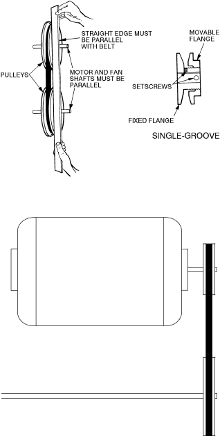
Fig. 81 — Blower Motor Pulley Adjustment

Fig. 82 — Belt Alignment

Variable Air Volume Option — This option can be used in conjunction with the CO2 sensor option (ordered separately). Outside air and exhaust air blower speeds are independently controlled by variable frequency drives and modulated based upon space occupancy, which can be measured by CO2. The more people in the space the greater the CO2 levels, the more outside air is introduced. This option eliminates over ventilating the space in less than full condi- tions. The ERV unit has completely different electrical charac- teristics when used with a variable air volume option. Refer to Tables 2 and 3.

Operating Sequence

OCCUPIED MODE — While in occupied mode, the 62M ERV will operate per the ERV Timer option (scheduling program), the CO2 sensor input, a combination of the schedul- ing option and CO2 input, or the economizer accessory. Additionally, the low temperature lockout (LTLO) function locks out the 62M ERV if the outdoor-air temperature entering the wheel is below the set point. The LTLO is factory set at –10 F, and can be field adjusted from –30 F to 100 F.

Occupied Mode, with CO2 Sensor — When the CO2 sensor is used, it will measure the space CO2 levels in parts per million (ppm). The 62M ERV CO2 setting is factory set at 1,000 ppm but can be adjusted from 0 ppm to 2,000 ppm. When either the scheduling program and/or the CO2 sensor calls for ERV operation, the ERV will activate the following:

ERV wheel

Outdoor air blower motor

EXH blower motor

Two-position damper opens

NOTE: The two-position damper option may slightly delay activation of the ERV blower motor.

Occupied Mode, with Frost Protection — In the occupied mode, the frost protection option will eliminate frost build-up on the ERV wheel using exhaust air. It is activated via a pressure differential across the ERV wheel. This set point is field set from 0.2 in. wg to 2.0 in. wg and must be set to 150% of the normal static pressure across the wheel. The frost protec- tion feature is automatically locked out above 35 F.

NOTE: If the outdoor-air temperature is below 35 F, a dirty wheel may incorrectly activate the frost control feature if the differential pressure across the wheel exceeds the set point.

When the frost protection option is activated the following will occur:

ERV wheel turns on.

Outdoor air blower motor turns off.

EXH blower motor is on.

Occupied Mode, with the Pre-Heat Option — In the occu- pied mode, the pre-heat option provides frost protection for the ERV wheel and slightly warms the outdoor air. This feature is factory set to activate at –5 F, and can be field adjusted from –30 F to 100 F. It is recommended that this set point be set at the frost threshold for the region in which it is used.

If desired, this feature may also be activated via a field supplied pressure differential switch to determine if frost build up has occurred on the ERV wheel.

Occupied Mode, with the Economizer Accessory — When using the economizer option, this allows for up to 100% outside air to be brought in for free cooling. During free cooling, the rooftop unit mechanical cooling may or may not be operating depending on the set points used with the rooftop unit. When using the economizer accessory, it is recommended that the minimum position be set to the closed position and the ERV should be set such that it is locked out when the econo- mizer opens far enough to bring in the same level of outdoor air as the ERV.

If desired, this feature may also be activated via a field-supplied pressure differential switch to determine if frost build- up has occurred on the ERV wheel.

During free cooling, the following occurs:

ERV wheel is turned off.

Outdoor air blower is turned off.

EXH blower motor turns on.

Two-position outdoor-air damper is closed (if used).

Two-position EXH damper is opened (if used).

Stop/jog option will periodically rotate the ERV wheel to clean it during wheel bypass operation. This feature is factory set to activate every 10 minutes, for 20 seconds of operation. Both settings can be adjusted from 0 to 10 minutes.

Wheel Bypass Option — When using the wheel bypass option (with the stop/jog option), this allows free cooling through the wheel limited by the ERV airflow cfm limits. With this option the unit can be in free cooling or not depending on the tempera- ture of the outdoor-air compared to the set point. When not in free cooling, the ERV will not operate. When in free cooling:

ERV wheel is turned off.

Outdoor-air blower is turned on.

74

Image 74
Contents Installation, Start-Up Service Instructions Assembling the Roof Curb All dimensions are in inches Roof curb shipped unassembled Roof Curb 62M040 for Stand-Alone ApplicationsDuct Sizes DimensionsDimensions 075,120 170-285†Field provided Dimensions 075,120 62M-A-CRB-14MC 30.562M-B-CRB-14MC 49.63 45.5 Required Service Clearances Front Rear Left Right62MD,ME040 Outdoor Unit Dimensions Front 27.5 Rear Left Right62MB,MC075,120 Indoor Unit Dimensions 39 in. service clearance required for ERV wheel removal62MD,ME075,120 Outdoor Unit Dimensions 55 in. service clearance required for ERV wheel removal View A-A62MD,ME170-285 Outdoor Unit Dimensions Required Service Clearances View A-A 62 in. service clearance required for ERV wheel removal62MD,ME330-640 Outdoor Unit Dimensions Rear Left 72 in. service clearance required for ERV wheel removalFront 62MD,ME750,950 Outdoor Unit Dimensions Top View RooftopUnit Curb 004-007Roof Curb Location Detail Unit Curb Support48/50PG 03-07 ReturnERV TOP View 67 3/848/50HJ,TF,TJ,TM Cannot be used. Use the 62M economizer instead 008,009 62M-ATR-HJ78-H 62M-A-CRB-14MC48/50PG Supply ReturnRooftop Unit Curb 62M-ATR-PG26-H Unit Curb Rooftop Unit CurbSide View A-A 62M-ATR-PG712-H78 1 012,014 62M-BTR-HJ1012-D 62M-B-CRB-14MC 62M-BTR-HJ36-D 62M-B-CRB-14MC008,009 62M-BTR-HJ78-D 62M-B-CRB-14MC 62M-BTR-HJ1012-H 62M-B-CRB-14MC 62M-BTR-HJ36-H 62M-B-CRB-14MC62M-BTR-HJ78-H 62M-B-CRB-14MC 48/50HJ Length is 891/16″ for 48/50TM028 units62M-BTR-HJ1525-D 62M-B-CRB-14S 015,017 62M-BTR-HJ1525-D 62M-B-CRB-14S62M-BTR-PG26-D 62M-A-CRB-14MC 62M-BTR-PG712-D 62M-A-CRB-14MCUnit 38 3/4 Curb Rooftop Unit Curb 38 3/4 49 5/8 ERV CurbCurb Detail 62M-BTR-PG26-H 62M-B-CRB-14MC 80 5 44 1120-28 62M-BTR-HG1525-H 62M-B-CRB-14MC 114.4 78.6 020-028 62M-BTR-HG1525-H 62M-B-CRB-14MC 114.4 78.648/50PG 20-28 62M-BTR-HG1525-D 62M-B-CRB-14MC 114.4 48/50HJ 020-028 62M-BTR-HG1525-D 62M-B-CRB-14MC 114.4Supply 012,014 62M-CTR-HJ1012-D 62M-C-CRB-14M62M-CTR-HJ1012-H 62M-C-CRB-14M 62M-CTR-HJ1012-HEC 62M-C-CRB-14MOptional Economizer Hood Exhaust hood Rooftop Unit AccessoryTransition Rooftop Unit Accessory 62M ERV Unit 62M330-640 74 1/448/50PG 08-14 62M-CTR-PG712-D 62M-C-CRB-14M 923/4 5315/16 62M ERV Unit ERV Curb ERV Energy Recovery Ventilator 60 11/32 ERV Curb48/50PG 20-28 62M-CTR-HG1525-H 62M-C-CRB-14M 114.4 48/50HJ 020-028 62M-CTR-HG1525-H 62M-B-CRB-14M 114.448/50PG 20-28 62M-CTR-HG1525-D 62M-C-CRB-14M 114.4 Hood rather than the bottom. The newHood will use the filters from the original 48/50HJ 020-028 62M-CTR-HG1525-D 62M-B-CRB-14M 114.4Rooftop Unit Economizer See Note Standard Rooftop Unit Curb 58 3/4 ERV Curb Rooftop Unit Curb 77 3/4 Outside airHood 62M Unit ERV Wheel ERV Curb 48/50A 020-060 62M-CTR-AJ2060-D 62M-C-CRB-14MERV Wheel Hood Used when coupled with 62M750,950 units62M ERV Unit Rooftop Standard factory economizer cannot be48/50PG 20-28 62M-DTR-HG1525-H 62M-D-CRB-14M 114.4 48/50HJ 020-028 62M-DTR-HG1525-H 62M-D-CRB-14M 114.4Relief Hood 62M750,950 ERV ERV CurbHood O/A Outdoor Air 48/50PG 20-28 62M-DTR-HG1525-D 62M-D-CRB-14M 114.4Unit 57 9/16 Curb 95.7 Rooftop Unit 62M ERV Unit86.25 Rooftop See curb Detail 77 3/4Side View Rigging Details Physical Data Make Electrical Connections Electrical Data Without VAV Option Size ERV Electrical Data With VAV Option NEC FLA MCA VFD Exhaust and Supply Power Supply PRE Disconnect Economizer End Switch Wiring Typical Wiring Schematic, High Voltage Secondary Energy Recovery VentilatorPrimary MCA Minimum Circuit AmpsHigh Voltage Low Voltage Disconnect Fiop START-UP 62M040-120 ERV Wheel Pressure Drop 62M550-950 ERV Wheel Pressure Drop* 62M550,640 62M750,95062M040 Supply Air Fan Performance Curves 62M075 Supply Air Fan Performance Curves 62M120 Supply Air Fan Performance Curves 2400 28002600 220062M225 Supply Air Fan Performance Curves 62M285 Supply Air Fan Performance Curves 4500 4000 4000 5500 50004500 3500 3000 2500500 000 000 50062M640 Supply Air Fan Performance Curves 62M750 Supply Air Fan Performance Curves 9000 8500 8000 7500 7000 6500 11500 11000 1050010000 9500 Blower Motor Pulley Adjustment Service Installing Wheel Segments 62M170-950 Units Motor WheelDrive Series wheelMaintenance Diameter Seal Adjustment Copyright 2006 Carrier Corporation Page START-UP Checklist