Craftsman 917.27384 To Level Mower Housing, To Replace Mower Blade Drive Belt, Belt Removal

Page 23

TO LEVEL MOWER HOUSING

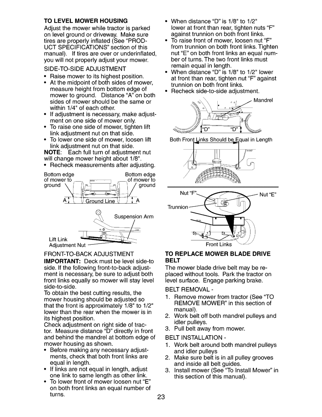
Adjust the mower while tractor is parked on level ground or driveway. Make sure

tires are properly inflated (See "PROD- UCT SPECIFICATIONS" section of this

manual). If tires are over or underinflated, you will not properly adjust your mower.

SIDE-TO-SIDE ADJUSTMENT

Raise mower to its highest position.

At the midpoint of both sides of mower, measure height from bottom edge of mower to ground. Distance "A" on both sides of mower should be the same or within 1/4" of each other.

If adjustment is necessary, make adjust- ment on one side of mower only.

To raise one side of mower, tighten lift link adjustment nut on that side.

To lower one side of mower, loosen lift

link adjustment nut on that side. NOTE: Each full turn of adjustment nut will change mower height about 1/8".

• Recheck measurements after adjusting.

Bottom edge


Bottom edge

of mower to

_.

of mower to

ground kk_l_l/


ground

Arm

When distance "D" is 1/8" to 1/2"

lower at front than rear, tighten nuts "F" against trunnion on both front links.

To raise front of mower, loosen nut "F" from trunnion on both front links. Tighten

nut "E" on both front links an equal num- ber of turns. The two front links must

remain equal in length.

When distance "D" is 1/8" to 1/2" lower

at front than rear, tighten nut "F" against trunnion on both front links.

Recheck side-to-side adjustment.

Both FronLinks Should be E.qual in Length

Jt"E"

Trunnio

LidfuLitrkent Nut_

Front Links

FRONT-TO-BACK ADJUSTMENT IMPORTANT: Deck must be level side-to side. If the following front-to-back adjust- ment is necessary, be sure to adjust both

front links equally so mower will stay level side-to-side.

To obtain the best cutting results, the mower housing should be adjusted so

that the front is approximately 1/8" to 1/2" lower than the rear when the mower is in

its highest position.

Check adjustment on right side of trac- tor. Measure distance "D" directly in front and behind the mandrel at bottom edge of mower housing as shown.

Before making any necessary adjust- ments, check that both front links are equal in length.

If links are not equal in length, adjust one link to same length as other link.

To lower front of mower loosen nut "E"

on both front links an equal number of turns.

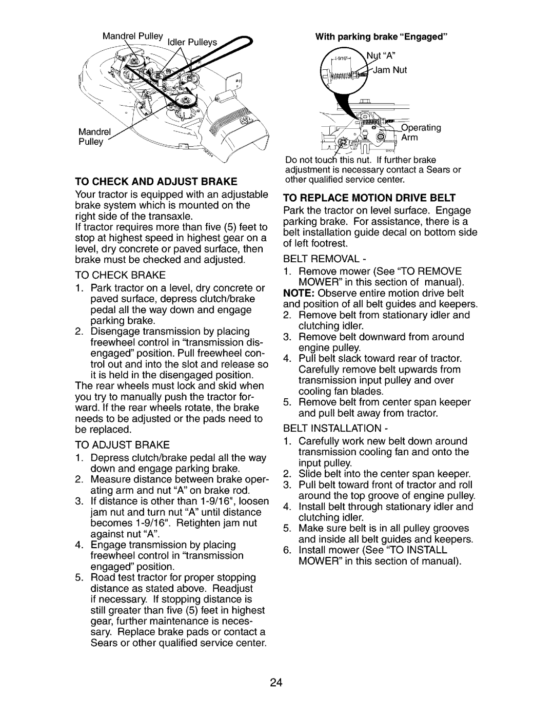
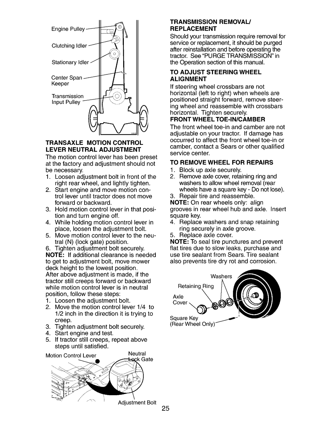
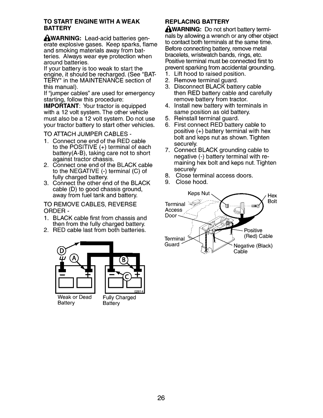
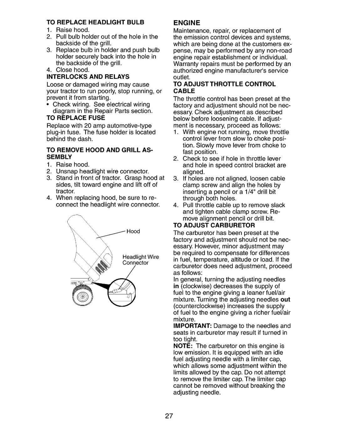
TO REPLACE MOWER BLADE DRIVE

BELT

The mower blade drive belt may be re- placed without tools. Park the tractor on level surface. Engage parking brake.

BELT REMOVAL -

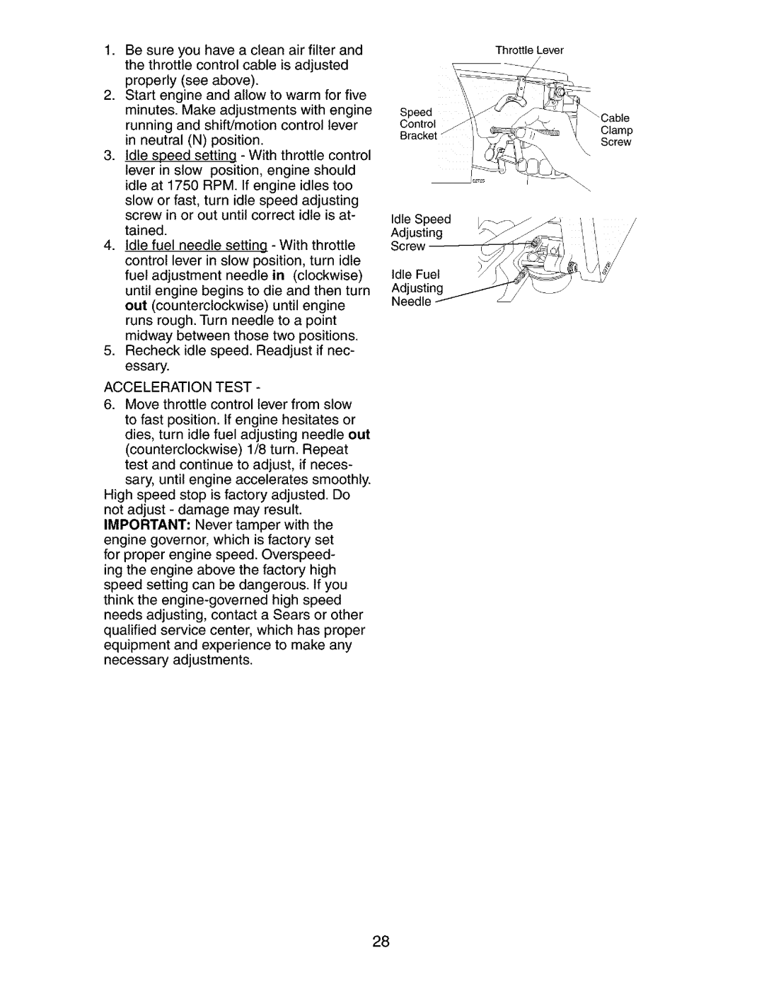
1.Remove mower from tractor (See "TO REMOVE MOWER" in this section of

manual).

2.Work belt off both mandrel pulleys and idler pulleys.

3.Pull belt away from mower.

BELT INSTALLATION -

1.Work belt around both mandrel pulleys and idler pulleys

2.Make sure belt is in all pulley grooves and inside all belt guides.

3.Install mower (See "To Install Mower" in this section of this manual).

23

Image 23 Contents
Jcriiftsmrnj Limited Warranty on Battery Limited Warranty on Craftsman Riding EquipmentGeneral Operation II. Slope OperationIII. Children IV. ServiceDo not Across Repair Protection Agreements Product SpecificationsSears Installation Service Customer ResponsibilitiesSlope Sheet Steering WheelTo Remove Tractor from Howto SET UP Your TractorTools Required for Assembly Check BatteryAssemble Gauge Wheels to Mower Deck Install SeatCheck Brake System Install Mulcher PlateCheck Deck Levelness Check for Proper Position of ALL BeltsAutomatic Models only Lift Lever Plunger Used to release Know Your TractorAttachment Clutch Lever Used To Move Forward and Backward HOW to USE Your TractorTo Adjust Mower Cutting Height To SET Parking BrakeDo not drive up or down To Adjust Gauge WheelsTo Operate Mower To Operate On HillsMents Before Starting the EngineTo Start Engine Transmission Engaged Transmission DisengagedPurge Transmission Automatic Transmission Warm UPMulching Mowing Tips Mowing TipsCheck tire pressure Lubrication ChartGeneral Recommendations Before Each USE To Sharpen Blade Battery Tractor Blade RemovalLubrication EngineTransaxle Pump Fluid AIR Filter Clean AIR INTAKE/COOLING AreasClean AIR Screen CleaningTo Remove Mower To Install MowerTractor Belt Removal To Level Mower HousingBelt Installation To Replace Mower Blade Drive BeltTo Replace Motion Drive Belt To Check and Adjust BrakeTo Adjust Brake To Remove Wheel for Repairs Transaxle Motion Control Lever Neutral AdjustmentTransmission Removal Replacement Front Wheel TOE-IN/CAMBERTo Remove CABLES, Reverse Order Replacing BatteryTo Attach Jumper Cables Engine To Adjustthrottle Control CableTo Replace Headlight Bulb Acceleration Test Cylinders BatteryFuel System Engine OILCause Correction Troubleshooting ChartIgnition switch Problem Cause Problem Cause Correction AMETdLUTCH Tractor - Model Number SchematicElectrical Tractor - Model NumberKEY Part Description Tractor - Model Number ElectricalTractor - Model Number 917.273840 Chassis and Enclosures Tractor - Model Number 917.273840 Chassis and Enclosures Tractor - Model Number Ground Drive 25/32 Tractor - Model Number 917.273840 Steering Assembly Tractor - Model Number 917.273840 Steeringassembly Control Throttle/Choke Tractor - Model Number EngineKEY Part Tractor - Model Number Seat AssemblyDescription Tractor - Model Number DecalsLink Front Tractor - Model Number Lift AssemblyTractor - Model Number Mower Deck 177563 Bracket, Deflector 124 351 64 \ 125 107 900 Ill 625 Cylinder HEAD, Valve and Breather Crankcase Headnalvbreathercrankcase Iiiiiiiiiiiiiiiiiii Not Illustrated Starting System OIL PAN/LUBRICATION OIL PAN/LUBRICATION KEY Part NO. no Iliiii 77% Crankshaft Page Suggested Guide for Sighting Slopes for Safe Operation Get it fixed, at your home or ours