7800 SERIES RELAY MODULES
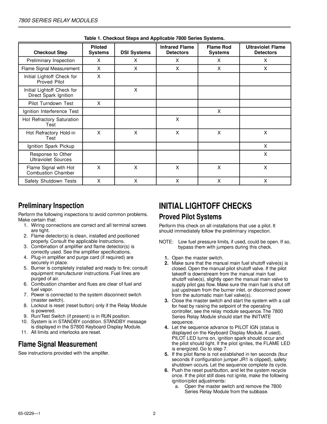
Table 1. Checkout Steps and Applicable 7800 Series Systems.
| Piloted |
| Infrared Flame | Flame Rod | Ultraviolet Flame |
Checkout Step | Systems | DSI Systems | Detectors | Systems | Detectors |
|
|
|
|
|
|
Preliminary Inspection | X | X | X | X | X |
|
|
|
|
|
|
Flame Signal Measurement | X | X | X | X | X |
|
|
|
|
|
|
Initial Lightoff Check for | X |
|
|
|
|
Proved Pilot |
|
|
|
|
|
|
|
|
|
|
|
Initial Lightoff Check for |
| X |
|
|
|
Direct Spark Ignition |
|
|
|
|
|
|
|
|
|
|
|
Pilot Turndown Test | X |
|
|
|
|
|
|
|
|
|
|
Ignition Interference Test |
|
|
| X |
|
|
|
|
|
|
|
Hot Refractory Saturation |
|
| X |
|
|
Test |
|
|
|
|
|
|
|
|
|
|
|
Hot Refractory | X | X | X | X | X |
Test |
|
|
|
|
|
|
|
|
|
|
|
Ignition Spark Pickup |
|
|
|
| X |
|
|
|
|
|
|
Response to Other |
|
|
|
| X |
Ultraviolet Sources |
|
|
|
|
|
|
|
|
|
|
|
Flame Signal with Hot | X | X | X | X | X |
Combustion Chamber |
|
|
|
|
|
|
|
|
|
|
|
Safety Shutdown Tests | X | X | X | X | X |
|
|
|
|
|
|
Preliminary Inspection
Perform the following inspections to avoid common problems. Make certain that:
1.Wiring connections are correct and all terminal screws are tight.
2.Flame detector(s) is clean, installed and positioned properly. Consult the applicable Instructions.
3.Combination of amplifier and flame detector(s) is correctly used. See the amplifier specifications.
4.
5.Burner is completely installed and ready to fire; consult equipment manufacturer instructions. Fuel lines are purged of air.
6.Combustion chamber and flues are clear of fuel and fuel vapor.
7.Power is connected to the system disconnect switch (master switch).
8.Lockout is reset (reset button) only if the Relay Module is powered.
9.Run/Test Switch (if present) is in RUN position.
10.System is in STANDBY condition. STANDBY message is displayed in the S7800 Keyboard Display Module.
11.All limits and interlocks are reset.
Flame Signal Measurement
See instructions provided with the amplifer.
INITIAL LIGHTOFF CHECKS
Proved Pilot Systems
Perform this check on all installations that use a pilot. It should immediately follow the preliminary inspection.
NOTE: Low fuel pressure limits, if used, could be open. If so,
bypass them with jumpers during this check.
1.Open the master switch.
2.Make sure that the manual main fuel shutoff valve(s) is closed. Open the manual pilot shutoff valve. If the pilot takeoff is downstream from the manual main fuel shutoff valve(s), slightly open the manual main valve to supply pilot gas flow. Make sure the main fuel is shut off just upstream from the burner inlet, or disconnect power from the automatic main fuel valve(s).
3.Close the master switch and start the system with a call for heat by raising the setpoint of the operating controller, see the relay module sequence. The 7800 Series Relay Module should start the INITIATE sequence.
4.Let the sequence advance to PILOT IGN (status is displayed on the Keyboard Display Module, if used), PILOT LED turns on, ignition spark should occur and the pilot should light. If the pilot ignites, the FLAME LED is energized. Go to step 7.
5.If the pilot flame is not established in ten seconds (four seconds if configuration jumper JR1 is clipped), safety shutdown occurs. Let the sequence complete its cycle.
6.Push the reset pushbutton, and let the system recycle once. If the pilot still does not ignite, make the following ignition/pilot adjustments:
a.Open the master switch and remove the 7800 Series Relay Module from the subbase.
2 |