3600 SERIES USER MANUAL
Explanation: The data range condition must be set.
7.) Close: Select “CLOSE” and return to the
4.10Explanation of the Interface Indicating Components
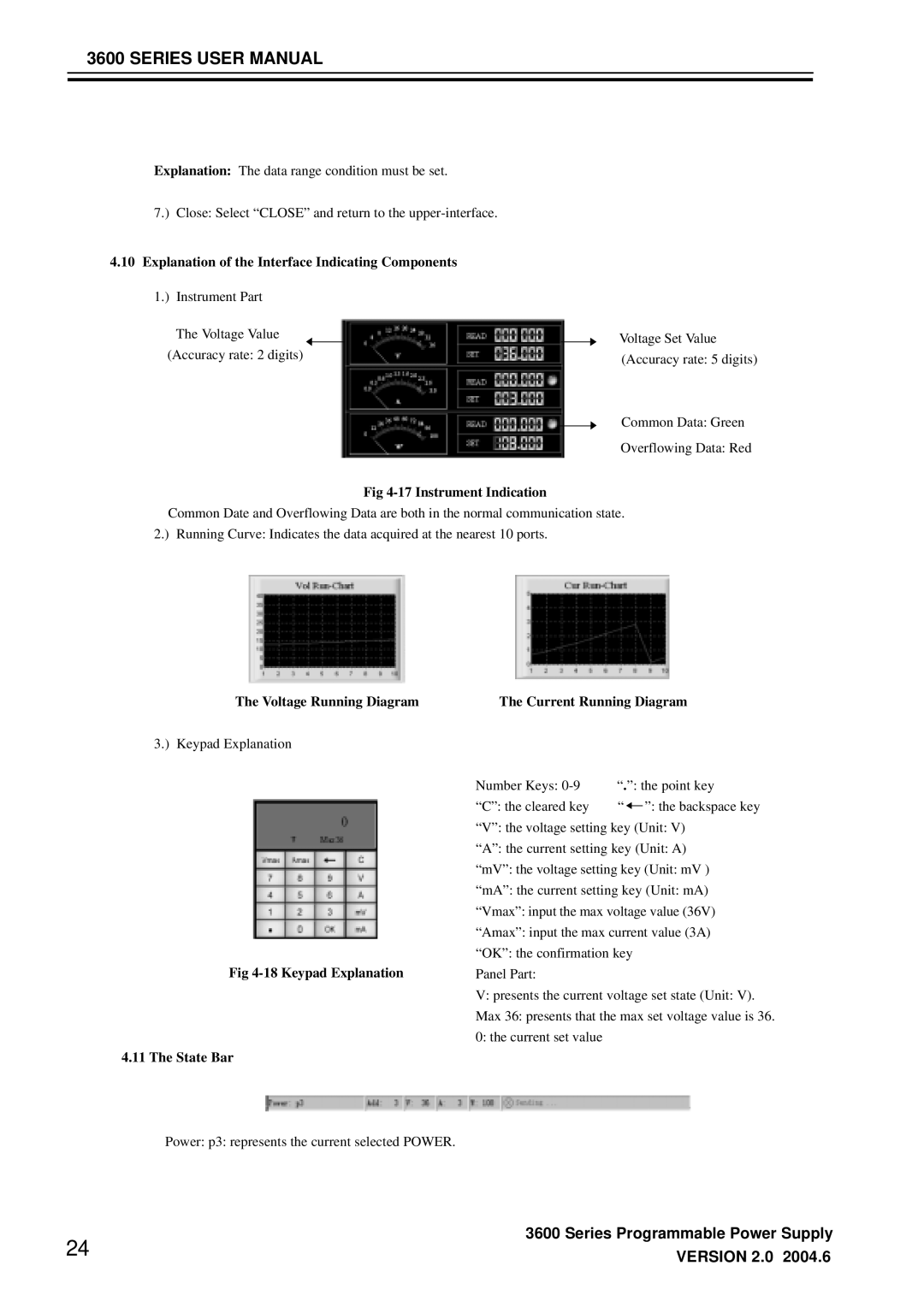
1.) Instrument Part
The Voltage Value (Accuracy rate: 2 digits)
Fig 4-17 Instrument Indication
Voltage Set Value (Accuracy rate: 5 digits)
Common Data: Green
Overflowing Data: Red
Common Date and Overflowing Data are both in the normal communication state. 2.) Running Curve: Indicates the data acquired at the nearest 10 ports.
The Voltage Running Diagram
3.) Keypad Explanation
Fig 4-18 Keypad Explanation
4.11 The State Bar
The Current Running Diagram
Number Keys: | “.”: the point key | ||
“C”: the cleared key | “ |
| ”: the backspace key |
| |||
“V”: the voltage setting key (Unit: V)
“A”: the current setting key (Unit: A)
“mV”: the voltage setting key (Unit: mV )
“mA”: the current setting key (Unit: mA)
“Vmax”: input the max voltage value (36V)
“Amax”: input the max current value (3A)
“OK”: the confirmation key Panel Part:
V:presents the current voltage set state (Unit: V). Max 36: presents that the max set voltage value is 36. 0: the current set value
Power: p3: represents the current selected POWER.
3600 Series Programmable Power Supply
24 | VERSION 2.0 2004.6 |
|