3600 SERIES USER MANUAL
1.4.2Structure
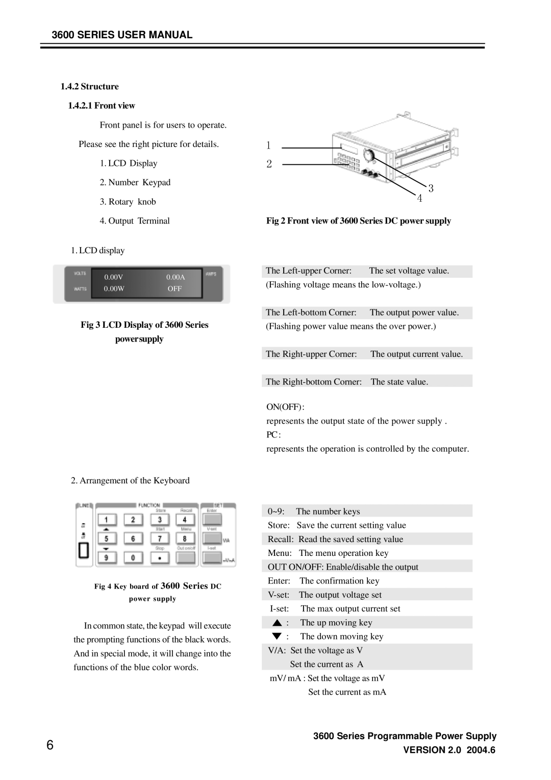
1.4.2.1Front view
Front panel is for users to operate. Please see the right picture for details.
1.LCD Display
2.Number Keypad
3.Rotary knob
4.Output Terminal
1.LCD display
0.00V0.00A
0.00WOFF
Fig 3 LCD Display of 3600 Series
powersupply
2. Arrangement of the Keyboard
Fig 4 Key board of 3600 Series DC
power supply
In common state, the keypad will execute the prompting functions of the black words. And in special mode, it will change into the functions of the blue color words.
6
Fig 2 Front view of 3600 Series DC power supply
The | The set voltage value. |
(Flashing voltage means the
The
(Flashing power value means the over power.)
The
The
ON(OFF) :
represents the output state of the power supply . PC :
represents the operation is controlled by the computer.
0~9: The number keys
Store: Save the current setting value
Recall: Read the saved setting value
Menu: The menu operation key
OUT ON/OFF: Enable/disable the output
Enter: The confirmation key
: The up moving key
: The down moving key
V/A: Set the voltage as V
Set the current as A mV/ mA : Set the voltage as mV
Set the current as mA
3600 Series Programmable Power Supply
VERSION 2.0 2004.6