Installing The Module |
Connecting the Cables
1
2
3
4
5
6
7
8
9
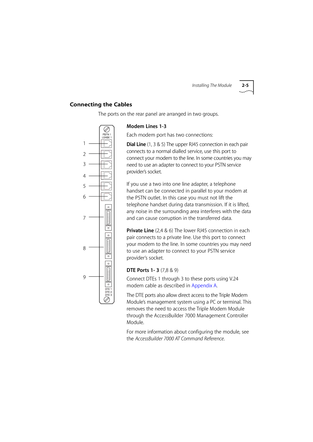
The ports on the rear panel are arranged in two groups.
Modem Lines
Each modem port has two connections:
Dial Line (1, 3 & 5) The upper RJ45 connection in each pair connects to a normal dialled service, use this port to connect your modem to the line. In some countries you may need to use an adapter to connect to your PSTN service provider’s socket.
If you use a two into one line adapter, a telephone handset can be connected in parallel to your modem at the PSTN outlet. In this case you must not lift the telephone handset during data transmission. If it is lifted, any noise in the surrounding area interferes with the data and can cause corruption in the transferred data.
Private Line (2,4 & 6) The lower RJ45 connection in each pair connects to a private line. Use this port to connect your modem to the line. In some countries you may need to use an adapter to connect to your PSTN service provider’s socket.
DTE Ports 1- 3 (7,8 & 9)
Connect DTEs 1 through 3 to these ports using V.24 modem cable as described in Appendix A.
The DTE ports also allow direct access to the Triple Modem Module’s management system using a PC or terminal. This removes the need to access the Triple Modem Module through the AccessBuilder 7000 Management Controller Module.
For more information about configuring the module, see the AccessBuilder 7000 AT Command Reference.