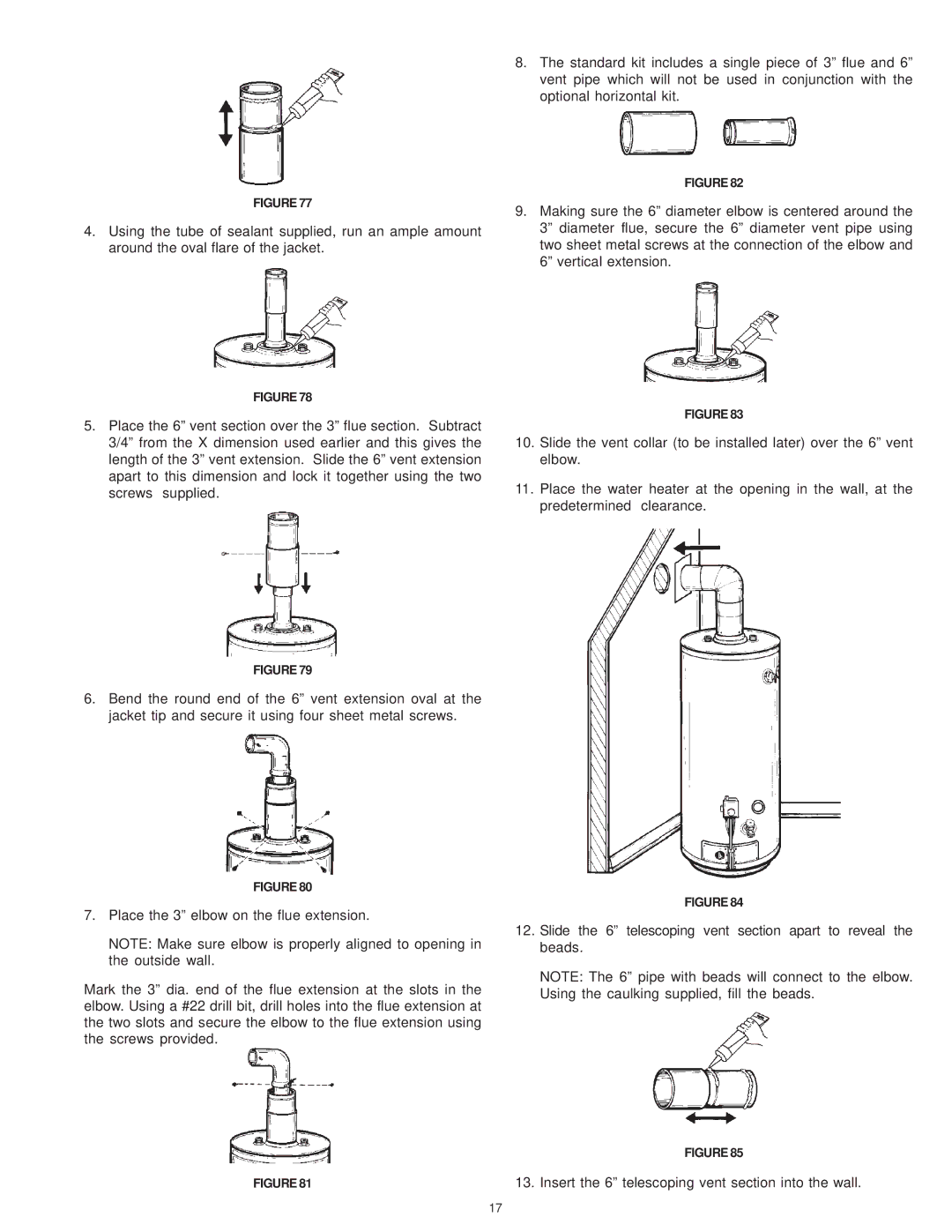
GDVH, XDVS, GDVS specifications
A.O. Smith is a leading manufacturer of water heating solutions, renowned for offering innovative products that cater to both residential and commercial needs. Among its impressive lineup, the GDVH, XDVS, and GDVS models stand out, showcasing advanced features and technologies that enhance performance and efficiency.The A.O. Smith GDVH series is designed for high-efficiency gas water heating. These units come equipped with the latest condensing technology, which allows them to utilize heat that would otherwise be lost in traditional systems. This process results in improved energy efficiency and significant cost savings on energy bills. The GDVH series is also noted for its EcoSmart feature, which adjusts the operational settings according to water usage patterns, further optimizing energy consumption.
The XDVS model, on the other hand, is a testament to A.O. Smith's commitment to durability and performance. Constructed with high-quality materials, the XDVS offers exceptional resistance against corrosion, thereby prolonging the lifespan of the unit. This model features advanced controls that provide real-time diagnostic information, enabling users to monitor performance and schedule maintenance effectively.
The GDVS series bridges the gap between affordability and performance. These water heaters are designed with a user-friendly interface, allowing for simple operation and easy adjustments. The GDVS models utilize a high-efficiency burner system that ensures rapid heating capabilities while keeping energy costs down. Additionally, the units are compact, making them ideal for homes with limited installation space, without compromising on output performance.
All three models incorporate A.O. Smith’s proven heating technologies that prioritize safety and efficiency. They feature advanced flame sensors and integrated safety controls that protect against overheating and ensure reliable operation. Furthermore, these models are compatible with various installation configurations, making them versatile options for diverse applications.
In conclusion, A.O. Smith's GDVH, XDVS, and GDVS water heaters present a blend of cutting-edge technology, rugged durability, and user-friendly features, catering to the needs of modern households and businesses. With energy efficiency as a hallmark of their design, these models not only promise excellent performance but also contribute to sustainable energy usage, making them an ideal choice for eco-conscious consumers.

