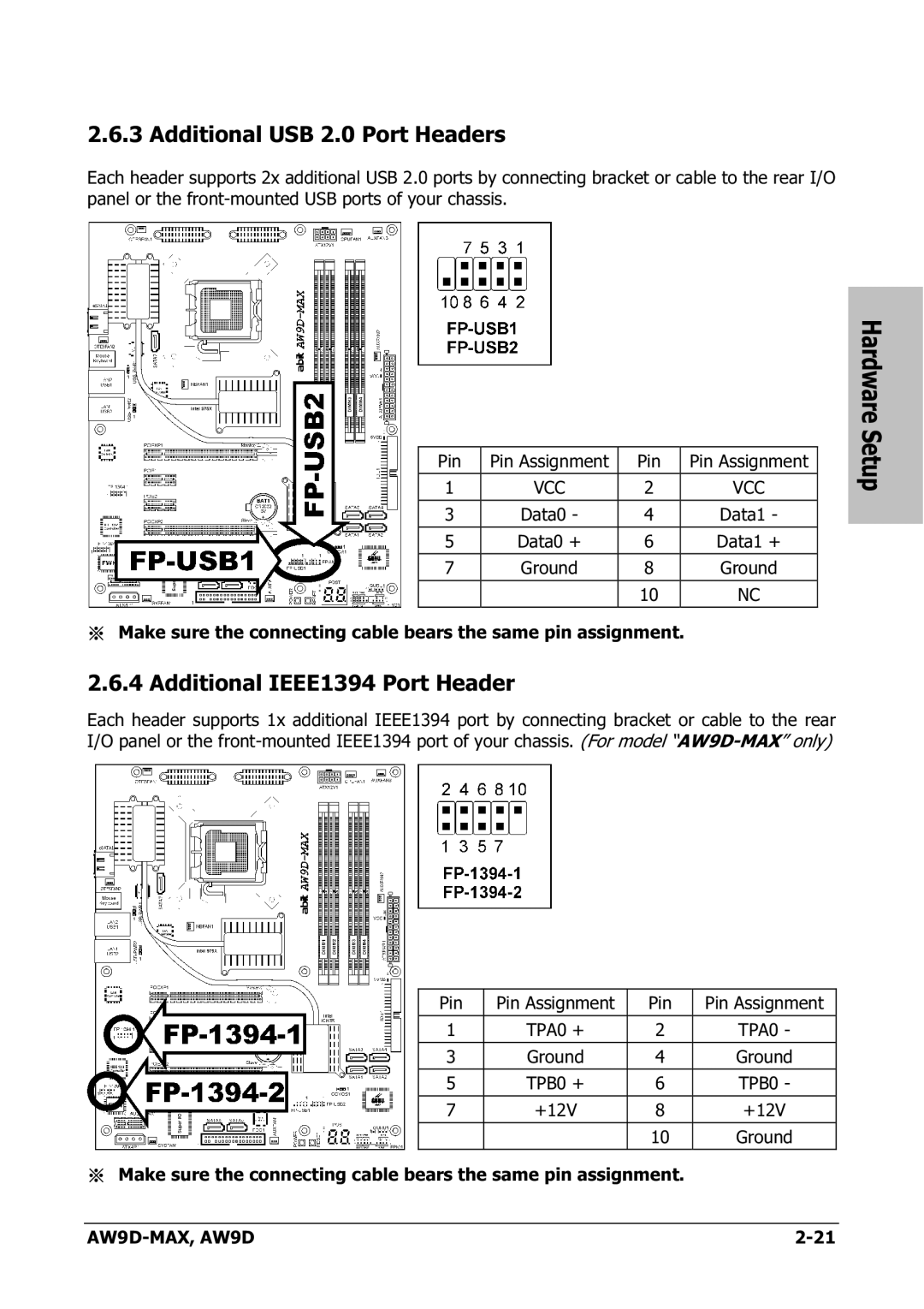
2.6.3 Additional USB 2.0 Port Headers
Each header supports 2x additional USB 2.0 ports by connecting bracket or cable to the rear I/O panel or the
|
|
|
|
| Hardware |
|
|
|
|
| Setup |
Pin | Pin Assignment | Pin | Pin Assignment |
| |
|
| ||||
1 | VCC | 2 | VCC |
|
|
|
|
|
|
|
|
3 | Data0 - | 4 | Data1 - |
|
|
|
|
|
|
|
|
5 | Data0 + | 6 | Data1 + |
|
|
7 | Ground | 8 | Ground |
|
|
|
| 10 | NC |
|
|
※Make sure the connecting cable bears the same pin assignment.
2.6.4 Additional IEEE1394 Port Header
Each header supports 1x additional IEEE1394 port by connecting bracket or cable to the rear I/O panel or the
Pin | Pin Assignment | Pin | Pin Assignment |
1 | TPA0 + | 2 | TPA0 - |
3 | Ground | 4 | Ground |
5 | TPB0 + | 6 | TPB0 - |
|
|
|
|
7 | +12V | 8 | +12V |
|
|
|
|
|
| 10 | Ground |
※Make sure the connecting cable bears the same pin assignment.
|