Chapter 3 | |
|
|
|
|
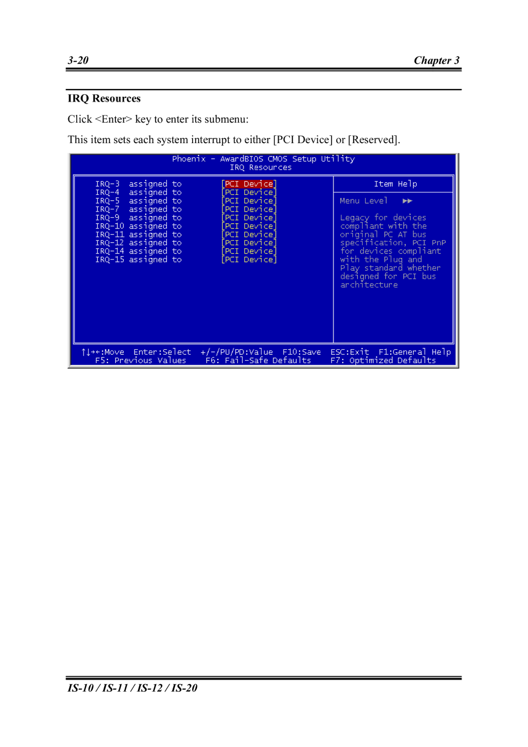
IRQ Resources
Click <Enter> key to enter its submenu:
This item sets each system interrupt to either [PCI Device] or [Reserved].
Chapter 3 | |
|
|
|
|
IRQ Resources
Click <Enter> key to enter its submenu:
This item sets each system interrupt to either [PCI Device] or [Reserved].