Manuals
/
Abit
/
Computer Equipment
/
Computer Hardware
Abit
IS-12 Serial ATA Connectors, These connectors each provide one Serial ATA channel connection
Models:
IS-12
IS-10
IS-11
IS-20
1
24
56
56
Download
56 pages
30.77 Kb
21
22
23
24
25
26
27
28
<
>
Specification
Install
Warranty
Memory Configuration Table
Problem Description
Hardware Setup
Pin 1-2 shorted default Normal operation
This header uses a jumper to adjust the CPU core voltage
When set to Auto, the BIOS will automatically check what kind of IDE drive you are using. If you want to define your own drive by yourself, set it to Manual and make sure you fully understand the meaning of the parameters. Refer to the manual provided by the device manufacturer to get the settings right
Front Panel Switches & Indicators Connection Headers
Page 24
Image 24
2-16
Chapter 2
2.4.12.
Serial ATA Connectors
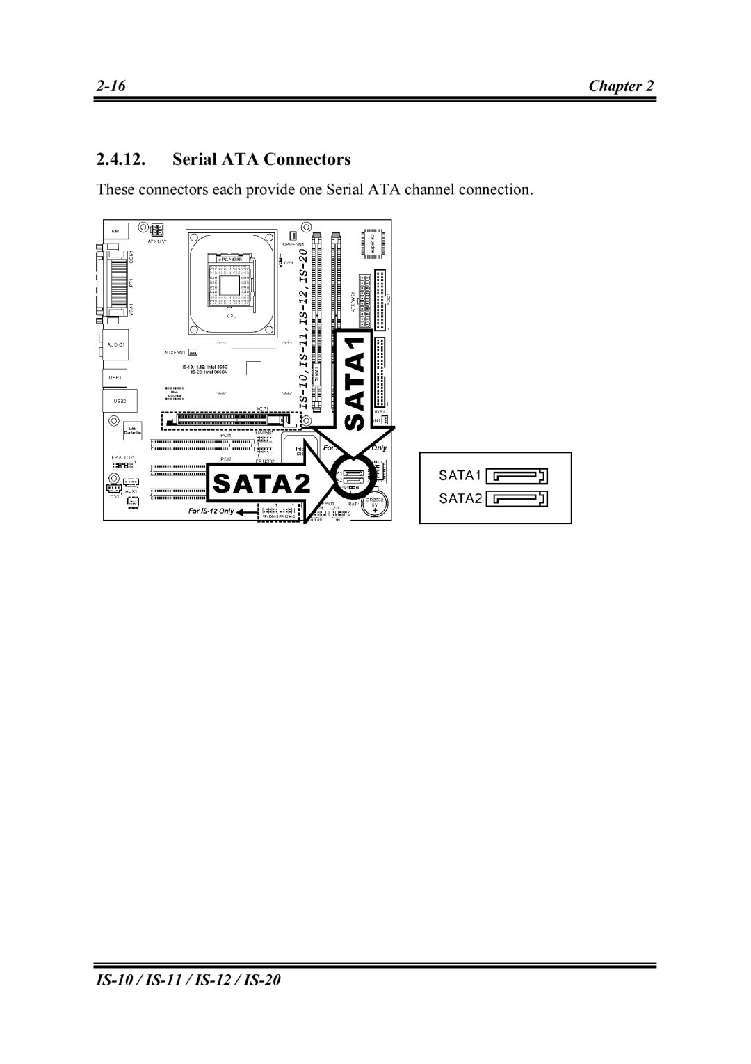
These connectors each provide one Serial ATA channel connection.
IS-10 /
IS-11 /
IS-12 /
IS-20
Page 23
Page 25
Page 24
Image 24
Page 23
Page 25
Contents
IS-10/IS-11/IS-12/IS-20
Intel Pentium 4 System Board Socket User’s Manual
4200-0383-03 Rev
Copyright and Warranty Notice
Hardware Setup
Chapter
Introduction
Table Of Contents
Driver Installation
Appendix A. How to Get Technical Support
BIOS Setup
Chapter
1.1. Features & Specifications
Chapter 1. Introduction
Internal I/O Connectors
External I/O Connectors
Miscellaneous
Chapter
1.2. Layout
Introduction
User’s Manual
1.3. Jumpers & Connectors Description
Chapter 2. Hardware Setup
2.1. Install The Motherboard
2.2. Install Pentium 4 CPU and Heatsink Supporting-Base
2.3. System Memory
2.3.1. Memory Configuration Table
2.3.2. Installing and Removing Memory Modules
2.4. Connectors, Headers, and Switches
2.4.1. ATX Power Connectors
2.4.2. FAN Power Connectors
Hardware Setup
Pin 1-2 shorted default Normal operation
2.4.3. CMOS Memory Clearing Header
This header uses a jumper cap to clear the CMOS memory
This slot supports an optional AGP graphics card up to AGP 4X/8X mode
2.4.4. AGP Display Card Slot IS-10/IS-11/IS-12
IS-10 / IS-11 / IS-12 / IS-20
2.4.5. Front Panel Switches & Indicators Connection Headers
2.4.6. Front Panel Audio Connection Header
Hardware Setup
2.4.7. Additional USB Port Connection Headers
2-11
These headers each provide two additional USB port connections
2.4.8. System Management Bus Connection Header
This header provides one additional System Management Bus connection
IS-10 / IS-11 / IS-12 / IS-20
2.4.9. Additional IEEE1394 Port Connection Headers IS-12
2.4.10. Internal Audio Source Connectors
IS-10 / IS-11 / IS-12 / IS-20
2.4.11. Floppy and IDE Disk Drive Connectors
2.4.12. Serial ATA Connectors
These connectors each provide one Serial ATA channel connection
IS-10 / IS-11 / IS-12 / IS-20
Hardware Setup
This header uses a jumper to adjust the CPU core voltage
Pin 1-2 shorted default Normal operation
2.4.13. CPU Core Voltage Selector
2.4.14. External I/O Panel Connectors
Chapter 3. BIOS Setup
Press DEL to run setup
3.1. Standard CMOS Features
Date mmddyy
Time hhmmss
IS-10 / IS-11 / IS-12 / IS-20
When set to Auto, the BIOS will automatically check what kind of IDE drive you are using. If you want to define your own drive by yourself, set it to Manual and make sure you fully understand the meaning of the parameters. Refer to the manual provided by the device manufacturer to get the settings right
Cylinder This item configures the numbers of cylinders Head
BIOS Setup
No Errors The system-boot will not stop for any error detected
Base Memory
Extended Memory
3.2. Advanced BIOS Features
Page
3.3. Advanced Chipset Features
BIOS Setup
This option enables or disables the on-chip VGA controller
AGP Aperture Size
Init Display First
3.4. Integrated Peripherals
Onboard IDE Device
BIOS Setup
This item enables or disables the onboard IDE-1 controller
This item enables or disables the onboard IDE-2 controller
SATA Only The SATA is operating in legacy mode
Serial ATA Port1 Mode / Serial ATA Port2 Mode
IS-10 / IS-11 / IS-12 / IS-20
Onboard PCI Device
SuperIO Device
BIOS Setup
KB Power ON Password
Hot Key Power ON
This item enables or disables the onboard FDD controller
Parallel Port Mode This item specifies the parallel port mode
3.5. Power Management Setup
Wake-Up by PCI card/LAN
3.6. PnP/PCI Configurations
IRQ Resources Click Enter key to enter its submenu
This item sets each system interrupt to either PCI Device or Reserved
IS-10 / IS-11 / IS-12 / IS-20
3-20
3.7. PC Health Status
3.8. Load Fail-Safe Defaults
3.9. Load Optimized Defaults
3.10. Set Supervisor Password
3.11. Set User Password
Chapter 4. Driver Installation
Driver Installation
User’s Manual
4.1. Setup Items
Appendix A. How to Get Technical Support
How to Get Technical Support
sold the product to you first
User’s Manual
Appendix A
alt.comp.periphs.mainboard.abit comp.sys.ibm.pc.hardware.chips
alt.comp.hardware.overclocking
IS-10 / IS-11 / IS-12 / IS-20
North America and South America
U.K. and Ireland
Japan
Shanghai
Russia
France, Italy, Spain, Portugal, and Greece
How to Get Technical Support
Thank You ABIT Computer Corporation
User’s Manual
Problem Description
Technical Support Form