Manuals
/
Abit
/
Computer Equipment
/
Computer Hardware
Abit
IS-11, IS-12, IS-20, IS-10
user manual
Layout
Models:
IS-12
IS-10
IS-11
IS-20
1
7
56
56
Download
56 pages
30.77 Kb
4
5
6
7
8
9
10
11
Specs
Install
Password
Memory Configuration Table
Hardware Setup
Internal I/O Connectors
Advanced Bios Features
ATX Power Connectors
Force Update Escd
Standard Cmos Features
Page 7
Image 7
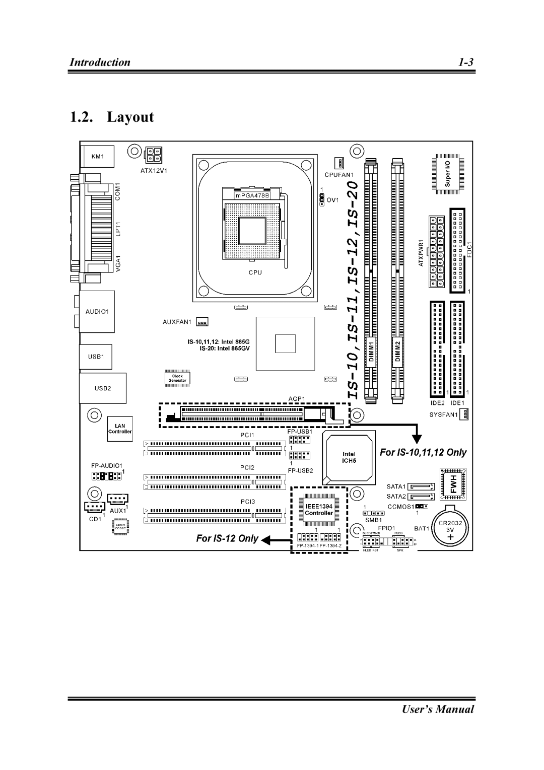
Introduction
1-3
1.2. Layout
User’s Manual
Page 6
Page 8
Page 7
Image 7
Page 6
Page 8
Contents
IS-10/IS-11/IS-12/IS-20
Page
Table Of Contents
Appendix A. How to Get Technical Support
Chapter Driver Installation
Chapter
Features & Specifications
External I/O Connectors
Internal I/O Connectors
Miscellaneous
Layout
CCMOS1
Jumpers & Connectors Description
Install The Motherboard
Hardware Setup
Install Pentium 4 CPU and Heatsink Supporting-Base
System Memory
Memory Configuration Table
Installing and Removing Memory Modules
ATX Power Connectors
Connectors, Headers, and Switches
FAN Power Connectors
Cmos Memory Clearing Header
AGP Display Card Slot IS-10/IS-11/IS-12
Front Panel Switches & Indicators Connection Headers
Front Panel Audio Connection Header
Additional USB Port Connection Headers
System Management Bus Connection Header
Additional IEEE1394 Port Connection Headers IS-12
Internal Audio Source Connectors
Floppy and IDE Disk Drive Connectors
Serial ATA Connectors
CPU Core Voltage Selector
AUDIO1
External I/O Panel Connectors
Press DEL to run setup
Bios Setup
Standard Cmos Features
User’s Manual
Chapter
Page
Hyper-Threading Technology
Advanced Bios Features
Page
Dram Timing Selectable
Advanced Chipset Features
Page
Onboard IDE Device
Integrated Peripherals
Page
SATA1 SATA2
Onboard PCI Device
SuperIO Device
Page
Chapter
Power Management Setup
Chapter
Force Update Escd
PnP/PCI Configurations
Chapter
PC Health Status
Set User Password
Load Fail-Safe Defaults
Load Optimized Defaults
Set Supervisor Password
Driver Installation
Setup Items
Appendix A. How to Get Technical Support
Appendix a
Ireland
North America and South America
Abit Computer Corporation
Japan
Shanghai
Russia France, Italy, Spain, Portugal, and Greece
Thank You Abit Computer Corporation
Technical Support Form
Top
Page
Image
Contents