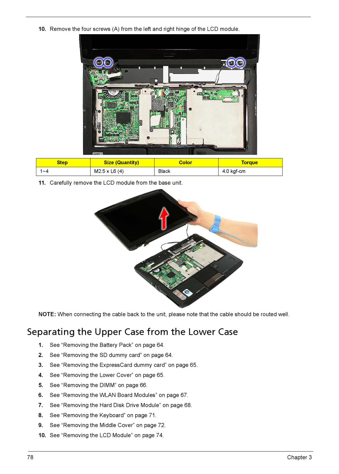
10.Remove the four screws (A) from the left and right hinge of the LCD module.
Step | Size (Quantity) | Color | Torque |
1~4 | M2.5 x L6 (4) | Black | 4.0 |
|
|
|
|
11.Carefully remove the LCD module from the base unit.
NOTE: When connecting the cable back to the unit, please note that the cable should be routed well.
Separating the Upper Case from the Lower Case
1.See “Removing the Battery Pack” on page 64.
2.See “Removing the SD dummy card” on page 64.
3.See “Removing the ExpressCard dummy card” on page 65.
4.See “Removing the Lower Cover” on page 65.
5.See “Removing the DIMM” on page 66.
6.See “Removing the WLAN Board Modules” on page 67.
7.See “Removing the Hard Disk Drive Module” on page 68.
8.See “Removing the Keyboard” on page 71.
9.See “Removing the Middle Cover” on page 72.
10.See “Removing the LCD Module” on page 74.
78 | Chapter 3 |