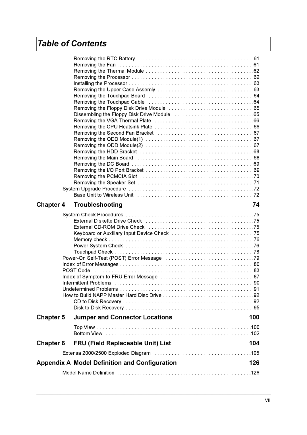
Table of Contents |
|
Removing the RTC Battery | . .61 |
Removing the Fan | . .61 |
Removing the Thermal Module | . .62 |
Removing the Processor | . .62 |
Installing the Processor | . .63 |
Removing the Upper Case Assemly | . .63 |
Removing the Touchpad Board | . .64 |
Removing the Touchpad Cable | . .64 |
Removing the Floppy Disk Drive Module | . .65 |
Dissembling the Floppy Disk Drive Module | . .65 |
Removing the VGA Thermal Plate | . .66 |
Removing the CPU Heatsink Plate | . .66 |
Removing the Second Fan Bracket | . .67 |
Removing the ODD Module(1) | . .67 |
Removing the ODD Module(2) | . .67 |
Removing the HDD Bracket | . .68 |
Removing the Main Board | . .68 |
Removing the DC Board | . .69 |
Removing the I/O Port Bracket | . .69 |
Removing the PCMCIA Slot | . .70 |
Removing the Speaker Set | . .71 |
System Upgrade Procedure | . .72 |
Base Unit to Wireless Unit | . .72 |
Chapter 4 Troubleshooting | 74 |
System Check Procedures | . .75 |
External Diskette Drive Check | . .75 |
External | . .75 |
Keyboard or Auxiliary Input Device Check | . .75 |
Memory check | . .76 |
Power System Check | . .76 |
Touchpad Check | . .78 |
. .79 | |
Index of Error Messages | . .80 |
POST Code | . .83 |
Index of | . .87 |
Intermittent Problems | . .90 |
Undetermined Problems | . .91 |
How to Build NAPP Master Hard Disc Drive | . .92 |
CD to Disk Recovery | . .92 |
Disk to Disk Recovery | . .95 |
Chapter 5 Jumper and Connector Locations | 100 |
Top View | .100 |
Bottom View | .102 |
Chapter 6 FRU (Field Replaceable Unit) List | 104 |
Extensa 2000/2500 Exploded Diagram | .105 |
Appendix A Model Definition and Configuration | 126 |
Model Name Definition . . . . . . . . . . . . . . . . . . . . . . . . . . . . . . . . . . . . . . . . . . . . . . .126
VII
