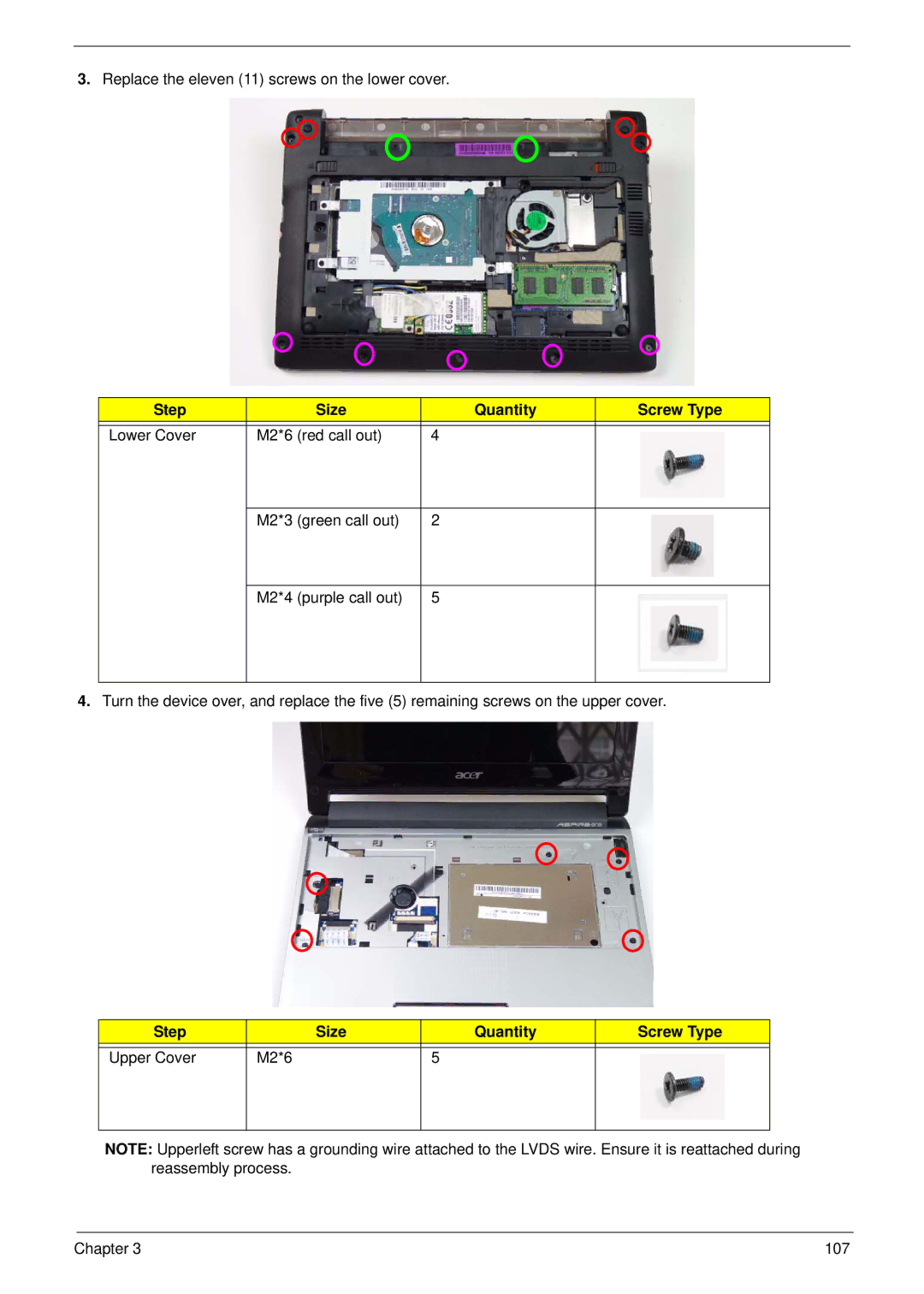
3.Replace the eleven (11) screws on the lower cover.
Step |
| Size | Quantity | Screw Type |
|
|
|
|
|
Lower Cover | M2*6 | (red call out) | 4 |
|
|
|
|
|
|
| M2*3 | (green call out) | 2 |
|
|
|
|
|
|
| M2*4 | (purple call out) | 5 |
|
|
|
|
|
|
4.Turn the device over, and replace the five (5) remaining screws on the upper cover.
Step |
| Size | Quantity | Screw Type |
|
|
|
|
|
Upper Cover | M2*6 |
| 5 |
|
|
|
|
|
|
NOTE: Upperleft screw has a grounding wire attached to the LVDS wire. Ensure it is reattached during reassembly process.
Chapter 3 | 107 |