Acer
TravelMate 6460/6410 Service Guide
Revision History
III
Copyright
Disclaimer
Screen Messages
Conventions
Preface
Chapter
Specification
Input Devices
Audio
Storage Subsystem
Communication
Environment
Power Subsystem
Dimensions and Weight
Security
Chapter
Calistoga
DiagramBlock
Description
Outlook Tour
Front View
Icon Description
Closed Front View
Right View
Left View
Base View
Rear View
Chapter
HDD
Indicators
Easy-launch Buttons
Easy-launch button Default application
FineTrack Basics
FineTrack and FineTrack buttons
Touchpad Basics
Touchpad
Lock Key Description
Using Acer FineTouch Keyboard
Desired access Num Lock on Num Lock off
Lock Keys and Embedded Numeric Keypad
Shift +
Windows keys
Hotkeys
Key Icon Description
US Dollar Sign
Euro Symbol
Special keys
Rotating the Acer OrbiCam
Acer OrbiCam
Launching the Acer OrbiCam
Changing the Acer OrbiCam Settings
Resolution
Options
Basic Settings
Camera Settings
Capturing Photos/Videos
Capture Settings
Using the Face Tracking Feature
Using the Acer OrbiCam as Webcam
Chapter
Empowering Technology Password
Acer Empowering Technology
Acer eNet Management
To Create a New Power Profile
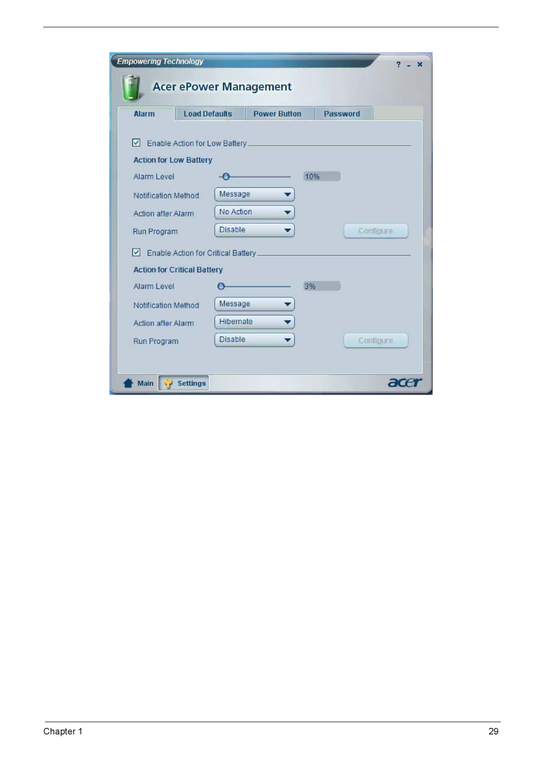
Acer ePower Management
AC Mode Adapter Mode
DC Mode Battery Mode
Chapter
Chapter
Acer ePresentation Management
Acer TPM-Based eDataSecurity Management
Chapter
Acer eSettings Management
Acer eRecovery Management
Chapter
Acer ePerformance Management
Acer GridVista dual-display compatible
Using the System Utilities
Launch Manager
Scans panel, click Run Full System Scan
Norton AntiVirus
How do I check for viruses?
North Bridge
Hardware Specification and Configuration
Specification
Processor
ICH7M
South Bridge
System Memory
Audio Codec & Amplifier
Wireless LAN
Keyboard
Modem
Toshiba
Pcmcia Express Card & Express Card
Hard Disk Drive
Seagate
WD1200BEVS WD1000BEVS WD800BEVS WD600BEVS
Hgst
Optical Disk Drive DVD Super Multi
Optical Disk Drive Combo
DVD-RAM 2.6GB
DVD-ROM, DVD-R
DVD+R, DVD+R DL DVD-R DL, DVD-R
DVD+RW, DVD-R
Lvds
LCD
CMO
LPL
LCD
3V Lvds
Samsung LTN150XB-L03-V
Cell
Battery
System Fan True Value Table
DBA
AC Adaptor
System Utilities
Bios Setup Utility
Uuid
Information
Parameter Description
Main
ECP
Advanced
Parameter Description Option
EPP
Security
Symbol Character Symbol Name
Slash
Boot
Exit
Before You Begin
General Information
SCREW-I20040M-BK-PATCH
Disassembly Procedure Flowchart
Description Acer Part No
Removing HDD Module
Disassembly Procedure
Removing Battery Pack
Removing RAM Modules and Mini PCI Card
Removing Optical Disk Drive and Pcmcia
Removing Keyboard
Removing Power Board and Modem Board
Removing LCD module from Main Unit
Separating Upper Case and Lower Case
Removing Main Board
Detaching CPU
Removing Thermal Module
Removing Touch Pad Board
Removing LCD Bezel
Detaching LCD Panel
Removing Inverter Board
Removing LCD Cable
Removing LCD Brackets
Troubleshooting
Keyboard or Auxiliary Input Device Check
System Check Procedures
External Diskette Drive Check
External CD-ROM Drive Check
Check the Battery Pack
Power System Check
Check the Power Adaptor
Touchpad Check
Error Message List
Power-On Self-Test Post Error Message
Index of Error Messages
Error Code List
CPU ID
Bios ROM
Dimm
See External Diskette Drive Check
LCD
Power System Check
Beep Code Post Code Description What to Check Recommended
Phoenix Bios Beep Codes
ROM
Beep Code Post Code Description What to Check Recommended
Beep Code Post Code Description What to Check Recommended
D0H
C0H
Beep Code Post Code Description What to Check Recommended
Power-Related Symptoms
Index of Symptom-to-FRU Error Message
LCD-Related Symptoms
Indicator-Related Symptoms
See Check the Battery Pack
Power Management-Related Symptoms
PCMCIA-Related Symptoms
Memory-Related Symptoms
Speaker-Related Symptoms
Modem-Related Symptoms
Peripheral-Related Symptoms
Keyboard/Touchpad-Related Symptoms
Intermittent Problems
Dimm
Undetermined Problems
Name Description
Top view
Smart card connector
JACK700
Bottom view
JACK701
JACK702
JACK704
JACK703
Jumper and Connector Location
Smart card connector
Bottom view
JACK704
FRU Field Replaceable Unit
CPU
Parts and Exploded Diagram
Battery
Photo Partname Descripton Acer Part no Adapter
Board
Photo Partname Descripton Acer Part no
Cable
Power Cord
CASE/COVER/BRACKET Assembly
Connector 2ND HDD SET,FPC+CONN,50P
Assembly Upper Case W/O FRU,TOP Case
Finger Printer Assembly
Middle Cover SET,COVER,SWITCH
DVD RW Drive
Combo Drive
HDD/HARD Disk Drive
FAN
Keyboard
Heatsink
Spanish
Keyboard Darfon KEYBOARD/W
ST,88,24P,BLACK,US International
Chinese
LCD
Communication Module
Memory
Camera
Mainboard
512MB Samsung MODULE,512MB,PC2
SO-DIMM DDRII533 256M Memory
Hynix HYMP532S64BP6 MODULE,256MB,PC2
512MB Nanya MODULE,512MB,PC2
Screw
Miscellaneous
Microphone
Speaker
I250100M4.5DX0.8T-BK