TravelMate 6492 Series Service Guide
Revision History
Copyright
Conventions
Preface
Page
Table of Contents
Machine Disassembly and Replacement
Jumper and Connector Locations 117
Page
Chapter
Features
Input devices
Power Subsystem
Audio
Communication
Environment
System Block Diagram
Ite Nam Description
Mainboard Layout
Top View
Cntr CN2 MDC Cntr USB
Bottom View
Name Description Ite
ODD Cntr
Name Description Ite
Front View
Your Acer Notebook tour
Icon Description
Closed Front View
Left View
Rear view
Right View
Base view
HDD
Indicators
Icon Function Description
Touchpad Basics
Launch key Default application
Easy-Launch Buttons
Page
Desired Access Num Lock On Num Lock Off
Using the Keyboard
Lock Keys and embedded numeric keypad
Lock Key Description
Windows Keys
Empowering Technology on
Hot Keys
Key Icon Description
US dollar sign
Euro symbol
Special Key
Acer eDataSecurity Management
Acer Empowering Technology
Chapter
Acer eLock Management
Acer ePerformance Management
Acer eRecovery Management
Acer eSettings Management
Acer Mode
Acer ePower Management
DC Mode
Create new power scheme
Chapter
Acer ePresentation Management
Launching the Acer OrbiCam
Acer OrbiCam
Getting to know your Acer OrbiCam
Changing the Acer OrbiCam settings
Enabling the Acer VisageON
Using the Acer OrbiCam as webcam
Capturing photos or videos
Page
Chapter
Acer GridVista dual-display compatible
Using the System Utilities
Launch Manager
CPU
Hardware Specifications and Configurations
Core System Description Specifications
North Intel 965GM North Bridge Package Fcbga 1299 balls
Core System Description Specifications
Audio Codec
LCD Power On Sequence
Bios ROM WX25X80VSSIG
Speaker Amplifier
PC card power controller chip for CB714
Audio Port
Pcmcia controller for Socket
Pointing Device
Port
Mini Card 802.11 a/g Module
Support on the System
Input Characteristics Functions Description
Power Plane Active Control Device State Signal
System LED Indicator
System LED Indicator
System Power States
Keyboard controller
Power Control Pin Description
Battery and Charger
State Output Pin
DC to DC Converter
DC-AC inverter
VCC-CORE
Parameter Min Typical Max Unit
AC adapter
Specification LiIon
Battery
Chapter
Navigating the Bios Utility
Chapter System Utilities Bios Setup Utility
Parameter Description
Information
Parameter Description
Main
Parameter Description Format/Option
F12Change Boot Device
ECP/SPP/EPP
Advanced
Parameter Description Option
Security
Clear or Set
Password Conventions
Symbol Character Symbol Name
Removing a Password
Setting a Password
Changing a Password
Chapter
USB CD/DVD ROM
Boot
Exit
Bios Flash Utility
Chapter
Before You Begin
General Information
Main Unit Disassembly Flowchart
Disassembly Procedure Flowcharts
LCM Module Disassembly Flowchart
Removing the CTO Cover
Main Unit Disassembly Procedure
Removing the Battery Pack
Removing the Btcb Screws
Removing the ODD
Removing the HDD
Removing the Memory Modules
Removing the Wireless Card
Removing the Switch Cover
Removing the Keyboard
Removing the Switch Board
Removing the Antenna Cables
Chapter
Removing the LCM Module
Removing the Mainboard
Removing the TouchPad
Page
Removing the Heatsink and Fan Module
Removing the CPU
Removing the LCM Bezel
LCM Module Disassembly Procedure
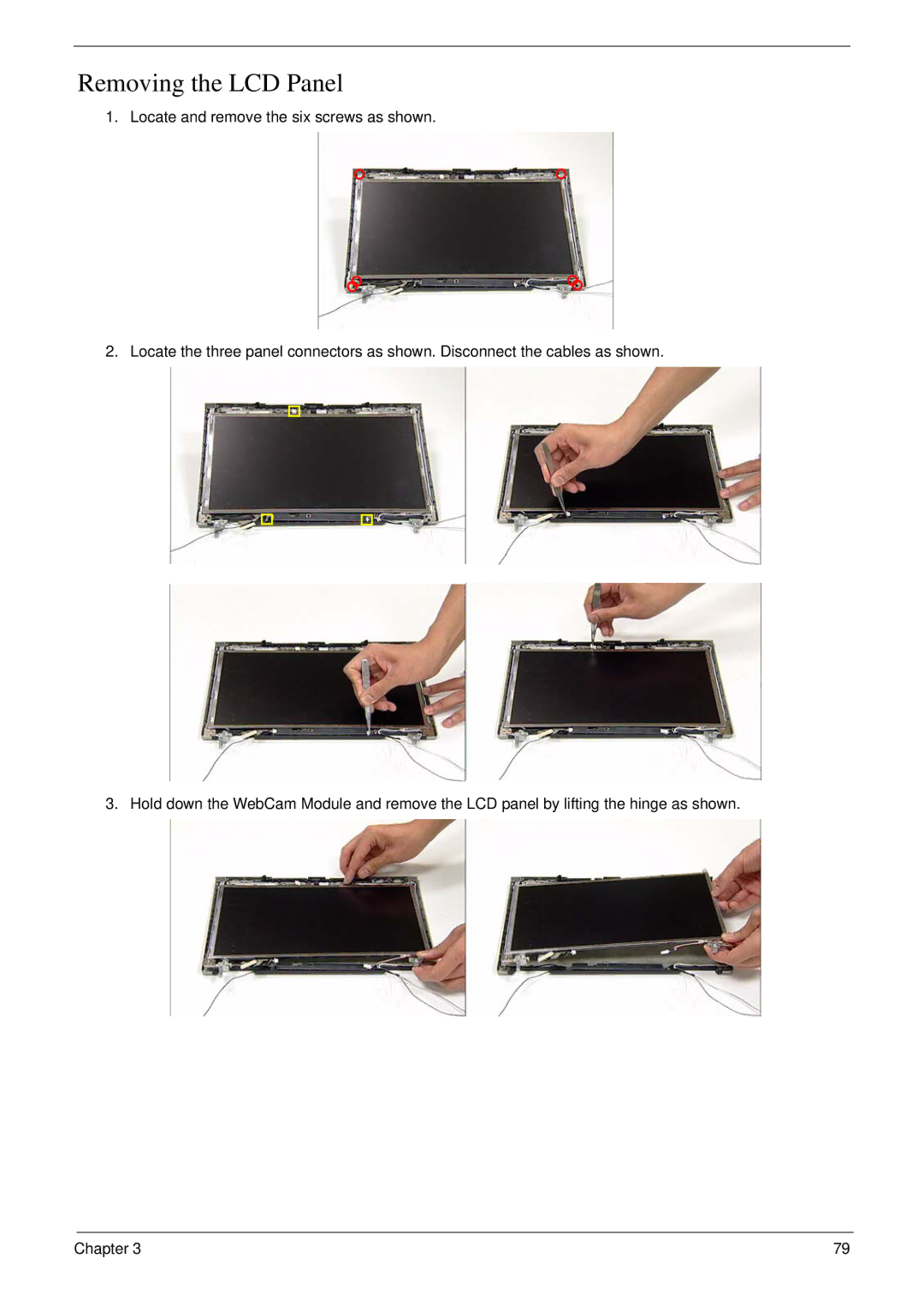
Removing the LCD Panel
Chapter
Page
Replacing the LCD Panel
LCM Module Reassembly Procedure
Page
Replacing the LCM Bezel
Replacing the Heatsink and Fan Module
Main Module Reassembly Procedure
Replacing the CPU
Replacing the Mainboard
Page
Replacing the LCM Module
Replacing the TouchPad
Replacing the Antenna Cables
Chapter
Replacing the Keyboard
Replacing the Switch Board
Chapter
Replacing the Wireless Card
Replacing the Switch Cover
Cable Color
Connector Number
Replacing the Memory Modules
Replacing the ODD
Replacing the Btcb Screws
Replacing the HDD
Replacing the CTO Cover
Replacing the Battery Pack
Symptoms Verified Go To
Troubleshooting
External Diskette Drive Check
System Check Procedures
External CD-ROM Drive Check
Keyboard or Auxiliary Input Device Check
Check the Battery Pack
Power System Check
Check the Power Adapter
Touchpad Check
Power-On Self-Test Post Error Message
Error Codes Error Messages
Index of Error Messages
Error Messages FRU/Action in Sequence
Bios ROM
CPU ID
Cmos Dimm
Post
No beep Error Messages FRU/Action in Sequence
LCD
Code Beeps Post Routine Description
Phoenix Bios Beep Codes
Setup
Code Beeps Post Routine Description
Code Beeps
Code
Symptom / Error Action in Sequence
Index of Symptom-to-FRU Error Message
Pcmcia
PCMCIA-Related Symptoms
Peripheral-Related Symptoms
Problems on Chapter 113
Intermittent Problems
Undetermined Problems
116 Chapter
Name Description
Connector Locations
Name Description CN29 IO Board Cntr D47 IR Receiver
CN4 LCD I/F Connector 40-PIN PIN No Signal name
Connector Pin Definitions
CN20 Touch PAD I/F Connector 12-PIN PIN No Signal name
CN12 Keyboard I/F Connector 25-PIN PIN No Signal name
CN27 Cardreader Connector-TD 43-PIN PIN No Signal name
PIN No Signal name
JACK501 RJ45&RJ11 Connector 14-PIN PIN No Signal name
CN7 CRT I/F Connector 15-PIN PIN No Signal name
CN513 Memory Connector 0 200-PIN PIN No Signal name
CN501 Fan Connector 3-PIN PIN No Signal name
CN504 Board to Board Connector 30-PIN PIN No Signal name
MABS#2
MACS#2
MAA9 MAA7 MAA8 MAA6
MAA5 MAA4 MAA3
MABS#0
MABS#1
MARAS#
MAWE#
CN512 Memory Connector 1 200-PIN PIN No Signal name
MBBS#2
MBCS#2
MBA9 MBA7 MBA8 MBA6
MBA5 MBA4 MBA3
CN511 Multi-Bay Connector 50-PIN PIN No Signal name
CN2 S-Video 7-PIN PIN No Signal name
CN506 RTC Battery Holder 2-PIN PIN No Signal name
CN22 USB Connector 4-PIN PIN No Signal name
CN510 HDD I/F Connector 22-PIN,SATA PIN No Signal name
CN19 PC Card Connector 68-PIN PIN No Signal name
MC973SBITCLK
CN28 MDC Connector 12-PIN PIN No Signal name
MC973SSDOUT GND MDC3V MC973SSYNC HAD3SSDIN1
CN24 MINI-PCI connector 124-PIN 1/2 PIN No Signal name
CN18 Internal Microphone Connector 2-PIN PIN No Signal name
CN32/33 Internal Speaker Connector 4-PIN PIN No Signal name
JACK3 External MIC Connector 6-PIN PIN No Signal name
JACK4 LineIn Connector 6-PIN PIN No Signal name
+VPACK +VACK BATTERY1IN BAT1DATA BAT1CLK GND
CN502 Battery Connector 7-PIN PIN No Signal name
132 Chapter
FRU Field Replaceable Unit List
Part Name Part Number Description
TravelMate 6492 Exploded Diagrams
3G Cover Ass’y
Batty Pack
Battery Ass’y
Label
MODULE, BLUETOOTH, USB
BlueTooth Ass’y
Module
Cable
Btcb Case Set Ass’y
Btcb Case Set
ASSEMBLY, CASE, BOTTOM, Offline
MN Speaker SET
BNI, Patch
CPU Ass’y
CTO Cover Set Ass’y
Display Ass’y
LCM Cable
Display Bezel Ass’y
Display Rear Ass’y
HDD Ass’y
KEYBOARD/W ST, 88, 24P, BLACK, US-INTL
Keyboard Ass’y
Keyb Acer MN
LABEL, BLANK, REEL, 60MM, 20MM
Memory Ass’y
Memory
Module Memory
MODEM, MDC, 56K, Azalia
Modem Ass’y
Modem
ODD Ass’y
Switch Cover Set Ass’y
Touchpad Bracket Set Ass’y
Tpcb CaseSet Ass’y
BUTTON, 4 WAY, Touch PAD, PC+ABS
WAY Button
Coat
Thpad Frame
Wireless Ass’y
Category Partname Descripton Acer Part
Parts List
Intel 4965AGN MOW2 Mini PCI
Cable Hotkey Board Cable
Heatsink CPU Heatsink Thermal MODULE,CPU
HDD/HARD Disk HDD 80GB 5400RPM Sata Seagate
Black Swedish ST,89,24P,BLACK,SWE
Black Traditional Chinese
CASE/COVER LCD Cover W/ Antenna FRU,LCD Bottom Case
CASE/COVER LCD Bracket Left HINGE-W
Patch Screw Screw BNI Patc
165
TravelMate 6492 Series
Appendix a
Model Country Acer Part no Description
HDD 1 GB
Appendix a
Appendix a 168
Umacf 2*512/160/BT/6L 101G16 5RNFP0.3DALES22 TM6492
Appendix a 170
AAP
Appendix a 172
USA
Appendix a 174
Appendix B
Test Compatible Components
Category Model/Description
Test Peripherals for TravelMate
Sampo PDP TV PM-42PS6
TV / LCD-TV
Sanwa JY-PFFUW
Epson Perfection 4870 Photo
Teac USB FDD FD05-PUB
ODD
MS Card 128MB
MMC MMC Card 64MB
SD Card 512MBSDSDJ-512
SM Card 128MB
Appendix C
Online Support Information
180