Manuals
/
Acer
/
Computer Equipment
/
Laptop
Acer
6530
manual
Chapter
Models:
6530
1
104
224
224
Download
224 pages
45.78 Kb
101
102
103
104
105
106
107
108
Troubleshooting
Specifications
System Block Diagram
Bluetooth
Password
Euro symbol
Indicators
Wireless LAN Bluetooth
Dimension
Common Problems
Page 104
Image 104
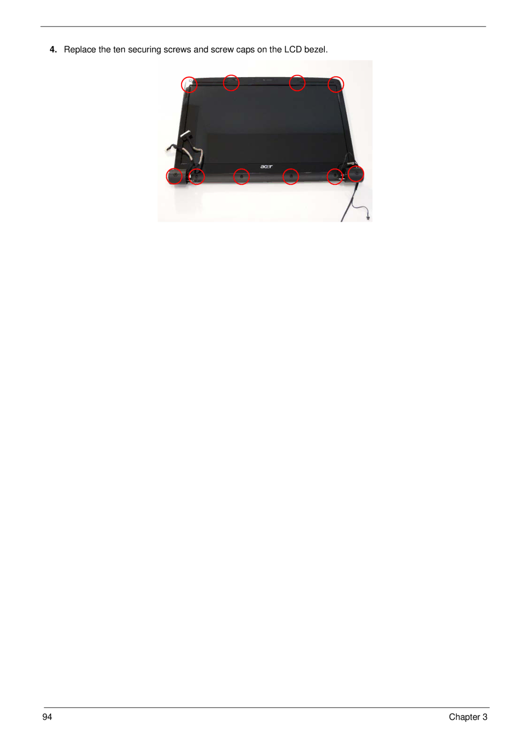
4.
Replace the ten securing screws and screw caps on the LCD bezel.
94
Chapter 3
Page 103
Page 105
Page 104
Image 104
Page 103
Page 105
Contents
Aspire 6530 Series Service Guide
Revision History
Copyright
III
Conventions
Preface
Page
Table of Contents
Troubleshooting 117
Viii
Peripheral Tests
Aspire 6530 Series
Microsoft Windows Vista Environment Test
Table of Contents
Features
Chapter
Dimensions and Weight
Storage subsystem
Audio
Communication
Power subsystem
Special keys and controls
Interface
Environment
System Block Diagram
Icon Description
Your Acer Notebook tour
Front View
VOL
Closed Front View
VOL +
Left View
Hdmi
Right View
Rear View
Bottom View
Indicators
Easy-Launch Buttons
Icon Function Description
Wlan
Touchpad Basics with fingerprint reader
Function Left Button Right Button Main touchpad
Using the Keyboard
Lock Keys and embedded numeric keypad
Windows Keys
Key Description
Hot Keys
Hotkey Icon Function Description
US dollar sign
Euro symbol
Special Key
Using the System Utilities
Acer GridVista dual-display compatible
Page
Hardware Specifications and Configurations
Processor Specification
Northbridge Specification
Smddrvtem
Southbridge Specification
System Clock Specification
Crystal and Oscillator Specification
System Memory Specification
Hard Disk Drive Interface Specification
Memory Combinations Slot Total Memory
DVD-ROM
Super-Multi Combo Module Specification
DVD-ROM DL, DVD-R DL / +R DL
Combo Drive Module Specification
2MB
DVD-RW DVD+RW CD-DA CD-ROM CD-ROM/XA
DMA
Thermal Control Specification
Bios ROM
LCD Specification
Lvds
VGA Subsystem Specification
Audio Codec and Amplifier Specification
MS-V122B-M82ME-XT
GPU AMD M82ME-XT/M86ME
Bluetooth Specification
MDC Module Specification
Battery Specification
SANYO/PANASONIC
Bios Setup Utility
Navigating the Bios Utility
Information
Parameter Description
Main
Parameter Description Format/Option
Disabled
Security
Parameter Description Option
Clear or Set
Setting a Password
Removing a Password
Changing a Password
Boot
IDE 0 Toshiba MK3252GSX-S1
Information Main Security Boot
Exit
Bios Flash Utility
USB HDD ABC
Chapter
Remove HDD/BIOS Utility
Remove HDD Password
Key in biospw 14452
Remove Bios Password
Chapter
Chapter
Machine Disassembly and Replacement
Disassembly Requirements
Pre-disassembly Instructions
Disassembly Process
General Information
Main Screw List Quantity Part Number
External Module Disassembly Process
External Modules Disassembly Flowchart
Screw List Step Quantity
Nylok Iron
Removing the Battery Pack
Removing the SD dummy card
Removing the ExpressCard dummy card
Removing the Lower Covers
HDD2
Removing the Dimm Modules
Removing the VGA Module
Step Size Quantity Screw Type VGA Module
Removing the TV Tuner Module
Removing the Wlan Module
Step Size Quantity Screw Type
Removing the Main Hard Disk Drive Module
Step Size Quantity Screw Type HDD Carrier M3*0.5+3.5I
Chapter
Removing the Optical Disk Drive Module
ODD Bracket M2.0*3.0-I Bkag
Removing the Secondary Hard Disk Drive Module
Step Size Quantity Screw Type HDD2 Carrier M3*0.5+3.5I
Main Unit Disassembly Process
Removing the Switch Cover
Removing the Power Board
Power Board M2.0*3.0-I Bkag
Removing the Keyboard
Removing the Speaker Module
Removing the Antenna Cables
Chapter
Removing the LCD Module
Bninylok
Removing the Upper Base
Unlock the connector and disconnect C as shown Chapter
Remove the ten securing screws on the top panel
Removing the Finger Print Reader
Removing the USB Board
Removing the Modem Module
Removing the Bluetooth Module
Page
Removing the Mainboard
Ninylok
Removing the Thermal Module
Removing the CPU
LCD Module Disassembly Process
Removing the LCD Bezel
Chapter
Disconnect the Mic cable and remove the LCD bezel Chapter
Removing the Inverter Board
Removing the Camera Module
Removing the LCD Panel
Removing the LCD Brackets and FPC Cable
LCD Brackets M2.0*3.0-I Bkag
LCD Module Reassembly Procedure
Replacing the LCD Panel
Chapter
Page
Connect the right Inverter board cable as shown
Replacing the LCD Bezel
Chapter
Replacing the Thermal Module
Main Module Reassembly Procedure
Replacing the CPU
Connect fan cable to the mainboard as shown
Replacing the Mainboard
Chapter
Replacing the Bluetooth Board
Replacing the Modem Module
Replacing the USB Board
Replacing the Finger Print Reader
Page
Replacing the Upper Cover
Page
Replacing the LCD Module
AC Power Cable LCD Power Cable
106 Chapter
Replacing the Speaker Module
Replacing the Keyboard
Replacing the Power Board
Replacing the Switch Cover
Turn the computer over and replace the ten screws as shown
Place the HDD in the HDD carrier
Replacing the Second Hard Disk Drive Module
Replacing the ODD Module
Replace the HDD connector Place the HDD in the HDD carrier
Replacing the Main Hard Disk Drive Module
Replacing the Wlan Module
Replacing the TV Tuner Module
Replacing the VGA Module
Replacing the Dimm Modules
Replacing the Lower Covers
Replacing the ExpressCard and SD Card Dummy Trays
Common Problems
Symptoms Verified Go To
Power On Issue
Computer Shutsdown Intermittently
No Display Issue
No Post or Video
Random Loss of Bios Settings
Abnormal Video Display
LCD Failure
Built-In Keyboard Failure
Touchpad Failure
Internal Speaker Failure
Sound Problems
Internal Microphone Failure
Microphone Problems
Select Set up microphone
HDD Not Operating Correctly
ODD Not Operating Correctly
Select Repair your computer
Select Startup Repair
Discs Do Not Play
Drive Not Detected
USB Failure Rightside
Modem Failure
External Mouse Failure
Other Failures
Dimm
Intermittent Problems
Undetermined Problems
Post Codes Tables
Code Beeps Post Routine Description
Display prompt Press F2 to enter Setup
Code Beeps Post Routine Description
Code Beeps For Boot Block in Flash ROM
Post Code Function Phase Component
Chipset Post Codes
PEI
MCH
DXE
Function Phase Component Code
Core Post Code Table
CEI / SEC
CEI / SEC CPU
DXE TCG
Biospsm DXE
Biospsm
LBT
0x42 Initialize interrupt vectors 0 thru 77h
0xC6 Initial and install console for UCR
Pico Bios
Bios
0xD9 Ipmi late init
0XDF
Sdxe
Jumper and Connector Locations
Top View
Bottom View
Clearing Password Check and Bios Recovery
Clearing Password Check
Steps for Clearing Bios Password Check
Hardware Open Gap Description
Bios Recovery by Crisis Disk
Bios Recovery Boot Block
Bios Recovery Hotkey
Steps for Bios Recovery by Crisis Disk
FRU Field Replaceable Unit List
TBD
Aspire 6530 Exploded Diagrams
Main Module
LCD Module
Battery
Aspire 6530 FRU List
Category Description Acer Part No Adapter
Board
Cable
Case/Cover/Bracket Assembly
Category Description Acer Part No
Multi Drive
Combo Drive
HDD Bracket Assy
HDD Connector
BS Sata LF F/WLV010J
Keyboard
LCD Cable
LCD Module 16 IN. Wxga W/CCD Wlan UMA
Inverter Board
LCD Cover Assy IMR W/BACKLIGHT MIC Antenna
LCD Bezel 16 IN. for CCD
LCD HINGE- R 16
LCD HINGE- L 16 IN. for UMA
Heatsink
Mainboard
Memory
Screw List
Category Description Acer Part No Miscellaneous
Screw List
Chapter 163
Appendix a
Aspire 6530 Series
Model Country Acer Part No Description
USA
AAP
TWN Gctwn
VHFFP0.3DHGEN11
China
Cbgndvbu
Emea
VHFFP0.3DHGES22
MC 82MEXTHM256TCOF 2*2G
VHFFP0.3DHGDE13
VHP32ATME4 MC 86MEH512COF
VHP32ATME9 MC 86MEH512COF
VHP32ATME3 MC 86MEH512COF
VHP32ATME2 MC 86MEH512COF
VHP32ATME6 MC 86MEH512COF
Model Country Acer Part No Description
171
Middle East LX.AUS0X.172 AS6530G-703G32Mn EM
Middle East LX.AUS0X.170 AS6530G-703G32Mn EM
Middle East LX.AUS0X.169 AS6530G-703G32Mn EM
175
Middle East LX.AUS0X.080 AS6530G-703G32Mn EM
177
Middle East LX.AUS0X.082 AS6530G-703G32Mn EM
Model
VGA Chip
SMPSI4025W N16WXGAG8 UMA SO1GBII6
ATRM70 N16WXGAG8 UMA SO2GBII6
AAQL60 N16WXGAG8 UMA SO2GBII6
AAQL60 N16WXGAG8 UMA SO2GBII6 SO1GBII6
AAQL60 N16WXGAG8 UMA SO1GBII6
ATRM70 N16WXGAG8 UMA SO2GBII6 SO1GBII6
ATUZM86 N16WXGAG8 UMA SO2GBII6 SO1GBII6
ATUZM82 N16WXGAG8 UMA SO2GBII6 SO1GBII6
SMPSI4025W N16WXGAG8 UMA SO2GBII6
ATUZM80 N16WXGAG8 82MEXTHM
ATRM70 N16WXGAG8 86MEHM
SO2GBII6 SO1GBII6
703G32Mn AS6530G
704G25Bn Appendix a 184
185
804G32Bn Appendix a 186
187
ATUZM86 N16WXGAG8 86MEHM
Wireless LAN Bluetooth
ATUZM82 N16WXGAG8 86MEHM
Model HDD 1 GB HDD 2 GB
NSM8XS
3rd WiFi 1x2 BGN 702G25Mn AS6530
NBDCB2XS
ODD
3rd WiFi 1x2 BGN 804G64Mn AS6530G
3rd WiFi 1x2 BGN 704G25Bn Appendix a 194
3rd WiFi BG 704G25Bn AS6530G
3rd WiFi 1x2 BGN 804G32Bn Appendix a 196
3rd WiFi BG 804G32Bn AS6530G
3rd WiFi 1x2 BGN 864G32Bn AS6530G
3rd WiFi 1x2 BGN 703G25Mn AS6530G
3rd WiFi 1x2 BGN 802G25Mi AS6530G
Test Compatible Components
Appendix B
Battery Test
Microsoft Windows Vista Environment Test
Vendor Type Description Adapter
CPU Test
Vendor Type Description
Hgst SG Sata LF F/WC40C
Seagate
Second HDD Test
Memory Test
ODD Test
VGA Test
Northbridge Chipset Test
WiFi Antenna Test
Bluetooth Test
Vendor Type Description Southbridge Chipset Test
Keyboard Test
Test Category Model
Peripheral Tests
Vendor Type Description Wlan Test
HD TV Hdmi
Ferguson DV3QSMC
LCD TV
Sclar
Nazar GPC-V70
HR8-U2M MS/MS-PRO/DUO
MP5125A DVD+RW/+R
Unique UA351-CB USB2.0/1394 HDD
Spdif
210
Online Support Information
Appendix C
212
Index
214
Top
Page
Image
Contents