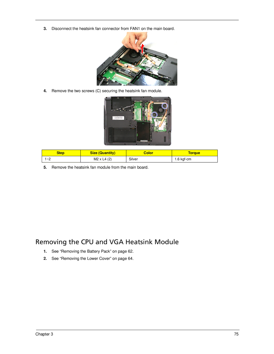
3.Disconnect the heatsink fan connector from FAN1 on the main board.
4.Remove the two screws (C) securing the heatsink fan module.
Step | Size (Quantity) | Color | Torque |
1~2 | M2 x L4 (2) | Silver | 1.6 |
|
|
|
|
5.Remove the heatsink fan module from the main board.
Removing the CPU and VGA Heatsink Module
1.See “Removing the Battery Pack” on page 62.
2.See “Removing the Lower Cover” on page 64.
Chapter 3 | 75 |
