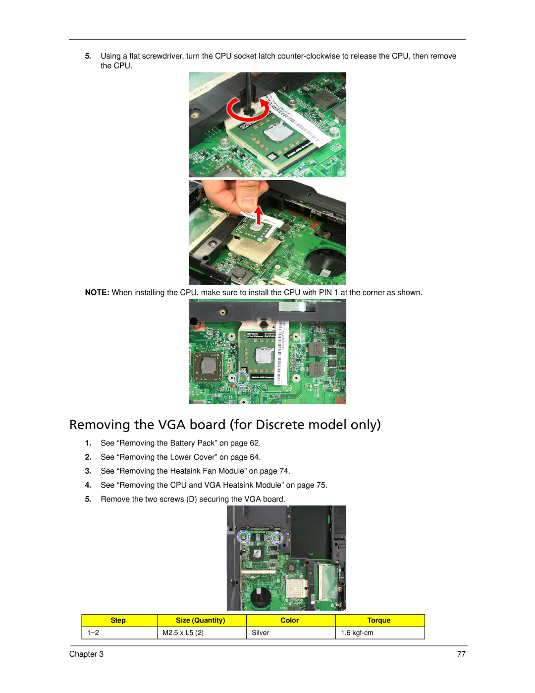
5.Using a flat screwdriver, turn the CPU socket latch
NOTE: When installing the CPU, make sure to install the CPU with PIN 1 at the corner as shown.
Removing the VGA board (for Discrete model only)
1.See “Removing the Battery Pack” on page 62.
2.See “Removing the Lower Cover” on page 64.
3.See “Removing the Heatsink Fan Module” on page 74.
4.See “Removing the CPU and VGA Heatsink Module” on page 75.
5.Remove the two screws (D) securing the VGA board.
| Step | Size (Quantity) | Color | Torque |
|
| 1~2 | M2.5 x L5 (2) | Silver | 1.6 |
|
|
|
|
|
|
|
|
|
|
|
|
|
Chapter 3 | 77 |
