English
22 | 2 System tour |
Front panel connectors
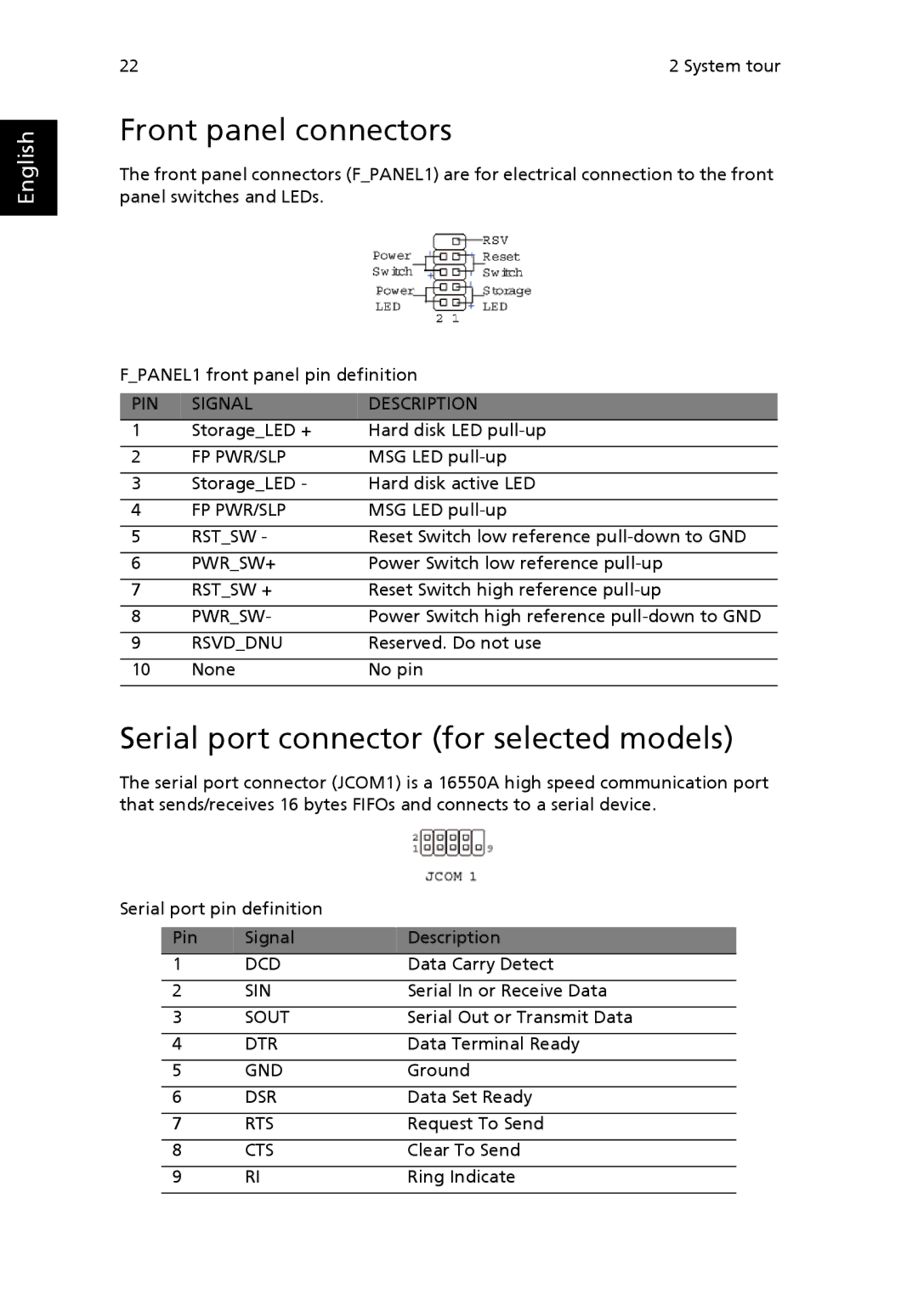
The front panel connectors (F_PANEL1) are for electrical connection to the front panel switches and LEDs.
F_PANEL1 front panel pin definition
PIN | SIGNAL | DESCRIPTION |
1 | Storage_LED + | Hard disk LED |
|
|
|
2 | FP PWR/SLP | MSG LED |
|
|
|
3 | Storage_LED - | Hard disk active LED |
|
|
|
4 | FP PWR/SLP | MSG LED |
|
|
|
5 | RST_SW - | Reset Switch low reference |
|
|
|
6 | PWR_SW+ | Power Switch low reference |
|
|
|
7 | RST_SW + | Reset Switch high reference |
|
|
|
8 | PWR_SW- | Power Switch high reference |
|
|
|
9 | RSVD_DNU | Reserved. Do not use |
|
|
|
10 | None | No pin |
|
|
|
Serial port connector (for selected models)
The serial port connector (JCOM1) is a 16550A high speed communication port that sends/receives 16 bytes FIFOs and connects to a serial device.
Serial port pin definition |
| ||
|
|
|
|
| Pin | Signal | Description |
| 1 | DCD | Data Carry Detect |
|
|
| |
| 2 | SIN | Serial In or Receive Data |
|
|
| |
| 3 | SOUT | Serial Out or Transmit Data |
|
|
| |
| 4 | DTR | Data Terminal Ready |
|
|
| |
| 5 | GND | Ground |
|
|
| |
| 6 | DSR | Data Set Ready |
|
|
| |
| 7 | RTS | Request To Send |
|
|
| |
| 8 | CTS | Clear To Send |
|
|
| |
| 9 | RI | Ring Indicate |
|
|
|
|
