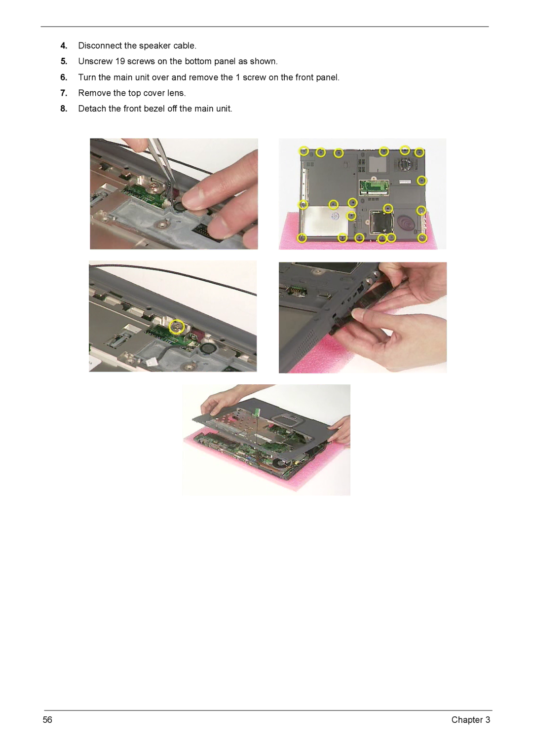
Manuals
/
Brands
/
Computer Equipment
/
Laptop
/
Acer
/
Computer Equipment
/
Laptop
Acer
VD.T25V7.001
- page 64
1
64
117
117
Download
117 pages, 38.76 Mb
56
Chapter 3
4.
Disconnect the speaker cable.
5.
Unscrew 19 screws on the bottom panel as shown.
6.
Turn the main unit over and remove the 1 screw on the front pane
l.
7.
Remove the top cover lens.
8.
Detach the front bezel off the main unit.
Contents
Main
Page
Copyright
Disclaimer
Conventions
Preface
Page
Table of Contents
Chapter 1 System Specifications 1
Chapter 2 System Utilities 33
Chapter 3 Machine Disassembly and Replacement 47
Page
System Specifications
Chapter 1
Features
Performance
Display
Keyboard and Pointing Device
I/O Ports
Page
4Chapter 1
Board Layout
Top View
Page
6Chapter 1
Outlook View
Front Open View
Chapter 1 7
Front Panel
8Chapter 1
Left Panel
Right Panel
10 Chapter 1
Rear Panel
Chapter 1 11
Bottom Panel
Indicators
Lock Keys
Embedded Numeric Keypad
Windows Keys
16 Chapter 1
Hot Keys
Page
The Euro Symbol
Launch Keys
Page
Touchpad
Touchpad Basics
22 Chapter 1
Hardware Specifications and Configurations
Processor
BIOS
Second Level Cache
System Memory
Chapter 1 23
Memory Combinations
LAN Interface
Modem/Bluetooth Interface
24 Chapter 1
Hard Disk Drive Interface
DVD-ROM Interface
Modem/Bluetooth Interface
Chapter 1 25
Combo Drive Interface
Audio Interface
Video Interface
26 Chapter 1
Video Memory
Parallel Port
IEEE 1394 Port
USB Port
Chapter 1 27
System Board Major Chips
Keyboard
Battery
LCD Inverter
28 Chapter 1
the system is on. LCD
AC Adapter
Chapter 1 29
Power Management
Environmental Requirements
Mechanical Specification
AC Adapter
30 Chapter 1
Memory Address Map
I/O Address Map
Mechanical Specification
Chapter 1 31
IRQ Assignment Map
DMA Channel Assignment
I/O Address Map
Page
System Utilities
Navigating the BIOS Utility
Chapter 2 35
Info.
Page
Chapter 2 37
System Devices
Security
Set User Password / Set Supervisor Password
Page
Removing a Password
Changing a Password
Primary Harddisk Security
Page
Exit
BIOS Flash Utility
System Diagnostic Diskette
Page
Chapter 3
Machine Disassembly and Replacement
Page
Page
50 Chapter 3
Screw List
Page
Page
Page
Page
Page
Page
Page
Page
Page
Disassembling External Modules
Disassembling the ODD Module
Page
Page
Troubleshooting
Chapter 4
System Check Procedures
External Diskette Drive Check
External CD-ROM/DVD-ROM Drive Check
Keyboard or Auxiliary Input Device Check
Memory Check
Power System Check
Check the Power Adapter
Check the Battery Pack
Touchpad Check
Display Check
Sound Check
Power-On Self-Test (POST) Error Message
70 Chapter 4
Index of Error Messages
Error Message List
Chapter 4 71
Error Message List
72 Chapter 4
Index of Symptom-to-FRU Error Message
LCD-Related Symptoms
Indicator-Related Symptoms
Power-Related Symptoms
Chapter 4 73
PCMCIA-Related Symptoms
Memory-Related Symptoms
Speaker-Related Symptoms
Power Management-Related Symptoms
74 Chapter 4
Peripheral-Related Symptoms
Keyboard/Touchpad-Related Symptoms
Modem-Related Symptoms
Intermittent Problems
Undetermined Problems
Chapter 4 77
Index of AFlash BIOS Error Message
Page
FRU (Field Replaceable Unit) List
Chapter 5
Page
Page
Page
Page
84 Chapter 5
Chapter 5 85
86 Chapter 5
Chapter 5 87
88 Chapter 5
Chapter 5 89
90 Chapter 5
Chapter 5 91
Page
Page
Model Definition and Configuration
Appendix A
Appendix A 93
TravelMate 800 Series
Main Features
Test Compatible Components
Appendix B
96 Appendix B
Microsoft Windows XP Environment Test
Appendix B 97
98 Appendix B
Appendix B 99
100 Appendix B
Microsoft Windows 2000 Environment Test
Appendix B 101
102 Appendix B
Appendix B 103
Page
Online Support Information
Appendix C
Page
Index