ADC AD-310 service manual Continuously

Models: AD-310

1 119
Download 119 pages 59.94 Kb
Page 46
Image 46

2)Ignitor and Flame-Probe Assembly

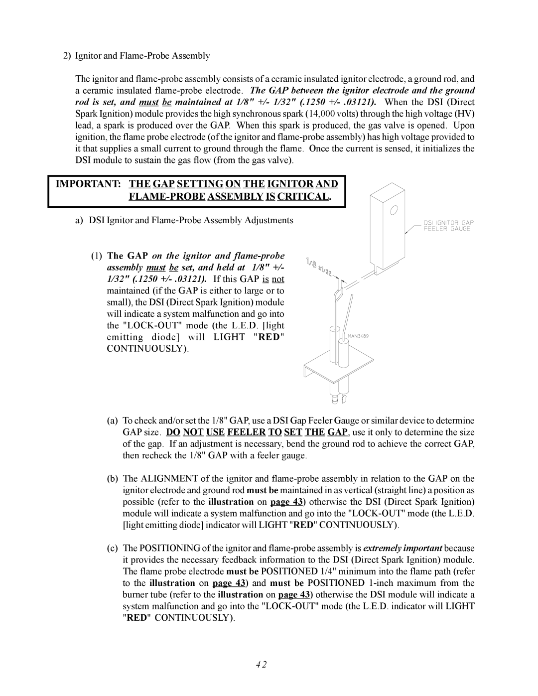
The ignitor and flame-probe assembly consists of a ceramic insulated ignitor electrode, a ground rod, and a ceramic insulated flame-probe electrode. The GAP between the ignitor electrode and the ground rod is set, and must be maintained at 1/8" +/- 1/32" (.1250 +/- .03121).When the DSI (Direct Spark Ignition) module provides the high synchronous spark (14,000 volts) through the high voltage (HV) lead, a spark is produced over the GAP. When this spark is produced, the gas valve is opened. Upon ignition, the flame probe electrode (of the ignitor and flame-probe assembly) has high voltage provided to it that supplies a small current to ground through the flame. Once the current is sensed, it initializes the DSI module to sustain the gas flow (from the gas valve).

IMPORTANT: THE GAP SETTING ON THE IGNITOR AND

FLAME-PROBE ASSEMBLY IS CRITICAL.

a) DSI Ignitor and Flame-Probe Assembly Adjustments

(1)The GAP on the ignitor and flame-probe assembly must be set, and held at 1/8" +/-

1/32" (.1250 +/- .03121).If this GAP is not maintained (if the GAP is either to large or to small), the DSI (Direct Spark Ignition) module will indicate a system malfunction and go into the "LOCK-OUT" mode (the L.E.D. [light emitting diode] will LIGHT "RED"

CONTINUOUSLY).

(a)To check and/or set the 1/8" GAP, use a DSI Gap Feeler Gauge or similar device to determine GAP size. DO NOT USE FEELER TO SET THE GAP, use it only to determine the size of the gap. If an adjustment is necessary, bend the ground rod to achieve the correct GAP, then recheck the 1/8" GAP with a feeler gauge.

(b)The ALIGNMENT of the ignitor and flame-probe assembly in relation to the GAP on the ignitor electrode and ground rod must be maintained in as vertical (straight line) a position as possible (refer to the illustration on page 43) otherwise the DSI (Direct Spark Ignition) module will indicate a system malfunction and go into the "LOCK-OUT" mode (the L.E.D. [light emitting diode] indicator will LIGHT "RED" CONTINUOUSLY).

(c)The POSITIONING of the ignitor and flame-probe assembly is extremely important because it provides the necessary feedback information to the DSI (Direct Spark Ignition) module. The flame probe electrode must be POSITIONED 1/4" minimum into the flame path (refer to the illustration on page 43) and must be POSITIONED 1-inch maximum from the burner tube (refer to the illustration on page 43) otherwise the DSI module will indicate a system malfunction and go into the "LOCK-OUT" mode (the L.E.D. indicator will LIGHT "RED" CONTINUOUSLY).

4 2

Page 46
Image 46
ADC AD-310 service manual Continuously

AD-310 specifications

The ADC AD-310 is a versatile and compact audio digital converter designed to meet the demands of audio professionals and enthusiasts alike. With its advanced technology and user-friendly features, the AD-310 stands out in the crowded marketplace of audio interface solutions.

One of the main features of the ADC AD-310 is its high-resolution audio conversion capabilities. Supporting sample rates up to 192 kHz and resolutions of up to 24 bits, the AD-310 ensures that audio captures are of the highest fidelity, making it ideal for recording, mixing, and mastering tasks. This level of detail is crucial for audio professionals who require precision and clarity in their audio signals.

Another standout characteristic of the ADC AD-310 is its robust connectivity options. It comes equipped with both USB and optical ports, enabling seamless integration with a variety of digital audio workstations (DAWs) and other audio equipment. This flexibility allows users to choose their preferred connection method, enhancing the overall workflow and efficiency during production.

The AD-310 also features advanced analog-to-digital and digital-to-analog converters, which contribute to its impressive dynamic range and low total harmonic distortion (THD). This ensures that the audio output is clean and true to the original signal, making it suitable for both recording and playback applications. Additionally, the unit incorporates real-time monitoring capabilities, allowing users to hear adjustments as they make them, ensuring the perfect mix every time.

For ease of use, the ADC AD-310 is designed with a simple, intuitive interface. Its layout includes clearly labeled controls and LED indicators, allowing users to quickly assess levels and settings at a glance. This design philosophy extends to its compact form factor, making it easy to transport and integrate into any studio setup, whether it be in a professional environment or home studio.

With its combination of high-quality audio processing, flexible connectivity, and user-friendly design, the ADC AD-310 is an excellent choice for anyone looking to elevate their audio production experience. Whether used by professionals or hobbyists, the AD-310 delivers performance and reliability that sets it apart in the audio converter market.