Manuals
/
ADC
/
Computer Equipment
/
Computer Hardware
ADC
MLN7400
manual
Setup EVB7400 Environments, Ethernet 10/100 BASE-T Connector
Models:
MLN7400
1
13
38
38
Download
38 pages
10.89 Kb
10
11
12
13
14
15
16
17
EVB7400 BLOCK DIAGRAM
External Timer0 Clock
Connecting EVB7400 and PC
Board Configuration
Reset System
pins 0f AC101L
GPIO Setting
Enable
Page 13
Image 13
Page 12
Page 14
Page 13
Image 13
Page 12
Page 14
Contents
MLN7400 Evaluation Board Manual
Version December 31 MCS Logic Inc
Cost Effective Network Processor for TCP/IP with ARM7TDMI
Copyright 2003 MCS LOGIC Limited. All rights reserved
Revision History
EVB7400
Revision Description
Version
3/36
4.2.1
Table of Contents
Downloading Binary Image
4.2.2
BLOCK DIAGRAM TOP VIEW
EVB7400 BLOCK DIAGRAM
PROPERTIES SETTING PAGE
CHOOSE SETTING PAGE
1.1 System Requirements
Chapter 1 Introduction
Fi gu re
ADDRESS
Fi gu re 3 BLOCK DIAGRAM TOP VIEW
1.2 Board Components
A Flash ROM
External Interrrupt Key
External Timer0 Clock
2.2 Boot ROM and ROM Bank0 length Selection SW2
Chapter 2 Board Configuration
2.1 Endian Selection SW1
2.3 NAND FLASH
128-TQFP/ 144 -LQFP Common I/O
2.4 GPIO Setting
144 -LQFP Extended I/O
선택적으로 사용
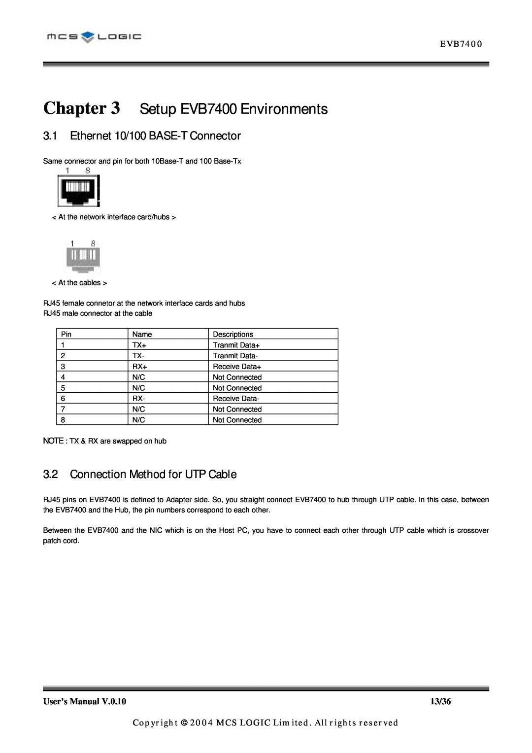
3.1 Ethernet 10/100 BASE-T Connector
Chapter 3 Setup EVB7400 Environments
3.2 Connection Method for UTP Cable
Fi gu re 4 UTP CABLE CONNECTION
4.1 Configuration the Hyper Terminal
Chapter 4 Connection Configurations for Debug Console
4.2.1 Downloading Binary Image
4.2 Downloading Binary Image and Flash Write
2. Type “8” at Flash Program Menu and type address to download
File Name Select the file name, which you want too download
3. select the Send File from the Transfer menu
Protocol Select the Xmodem or 1K Xmodem 4. Click Ok
Then, the file that you selected will be downloaded
4.2.2 Flash Write
5.2 Connecting EVB7400 and PC
Chapter 5 Opennice32 Installation
5.3 Powering up the Board and OPENice32
5.1 OPENice32
6.1 EVB7400 BOM
Chapter 6 EVB7400 1.0 Schemetic and BOM
GEOMETRY
COUNT
22/36
23/36
6.2 EVB7400 Schematic
MLN7400 Evaluation Board
BLOCK DIAGRAM
MLN7400EV
OPTIONAL
Endian Setting
LITTLE
SYSTEM CLOCK
MLN7400P128TQFP
JUMP
SPI EEPROM
IIC EEPROM
External Interrupt Test
EXTINT
MLN7400EN
FLASH
BANK2
SDRAM BANK
pin32 0f AC101L
pins 0f AC101L
Place close to
Place close to
UART1
UART0
UART2
UART3
PCMCIA INTERFACE
BANK3
POWER LED
JTAG CONNECTOR
RESET SYSTEM
7 Pin Ground
HEADER
IIC & SPI
DATA
HIGH SPEED
Disable
Enable
MUTE
JACK
AOUTL
AOUTR
AOUTR S
AOUTL S
MLN7400
NANDFlash
Top
Page
Image
Contents