Connections at the X200 (remote) module
1Place the X200 module adjacent to the remote user location.
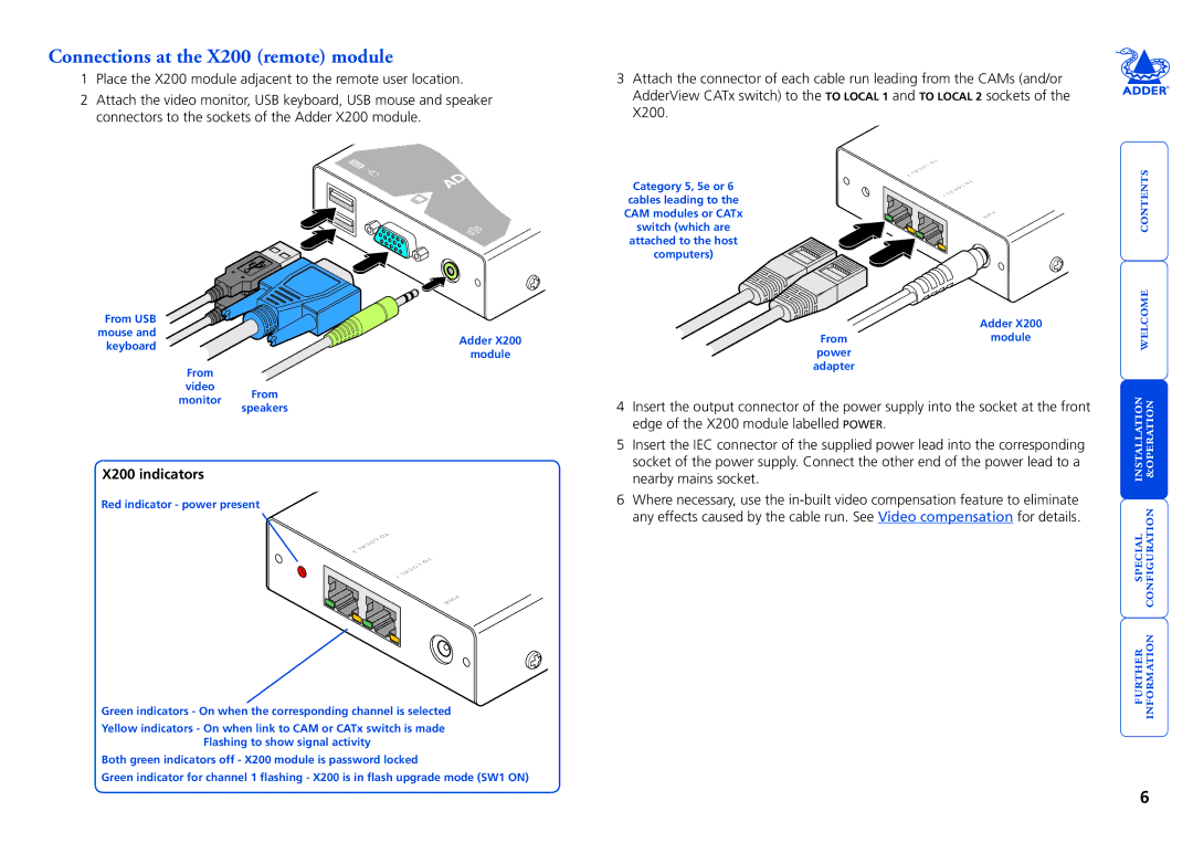
2Attach the video monitor, USB keyboard, USB mouse and speaker connectors to the sockets of the Adder X200 module.
3Attach the connector of each cable run leading from the CAMs (and/or AdderView CATx switch) to the TO LOCAL 1 and TO LOCAL 2 sockets of the X200.
ADD
From USB
mouse and
keyboardAdder X200 module
From
video
monitor From
Category 5, 5e or 6 cables leading to the CAM modules or CATx switch (which are attached to the host computers)
TO 2LOCAL
TO 1LOCAL
PWR
Adder X200
Frommodule power
adapter
welcome contents
speakers
X200 indicators
Red indicator - power present
LTO OCA 2L
LTO OCA 1L
PWR
Green indicators - On when the corresponding channel is selected
Yellow indicators - On when link to CAM or CATx switch is made Flashing to show signal activity
Both green indicators off - X200 module is password locked
Green indicator for channel 1 flashing - X200 is in flash upgrade mode (SW1 ON)
4Insert the output connector of the power supply into the socket at the front edge of the X200 module labelled POWER.
5Insert the IEC connector of the supplied power lead into the corresponding socket of the power supply. Connect the other end of the power lead to a nearby mains socket.
6Where necessary, use the
special installation configuration &