The HFAC supports the
¥ | 1242024L1 | ¥ | 1242002L7 |
¥ | 1242002L2 | ¥ | 1242029L1 |
¥ | 1242002L5 | ¥ | 1242029L2 |
¥ | 1242002L6 | ¥ | 1244001L1 |
¥ | 1245001L2 | ¥ | 1246001L2 |
¥ | 1245001L9 | ¥ | 1221001L2 |
¥ | 1245011L1 |
|
|
The differences in functionality when working with
The HFAC collects and presents performance information for each circuit deployed in the shelf. It also allows control of all provisioning information for each circuit. The unit can also be configured to provide advanced alarm processing features.
2. INSTALLATION
C A U T I O N !
SUBJECT TO ELECTROSTATIC DAMAGE
OR DECREASE IN RELIABILITY.
HANDLING PRECAUTIONS REQUIRED.
After unpacking the unit, inspect it for damage. If damage is discovered, file a claim with the carrier, then contact ADTRAN. See Warranty and Customer Service.
Electrical cable compliance
Table 1 shows the Compliance Codes for HFAC. The HFAC complies with the requirements covered under UL 1950 third edition and is intended to be installed in an enclosure with an Installation Code (IC) of ÒBÓ or ÒE.Ó
NOTE
This product is intended for installation in Restricted Access Locations Only. Input current at maximum load is 1A at
Table 1. Compliance Codes
Code Input Output
IC A -
TC - -
PC F C
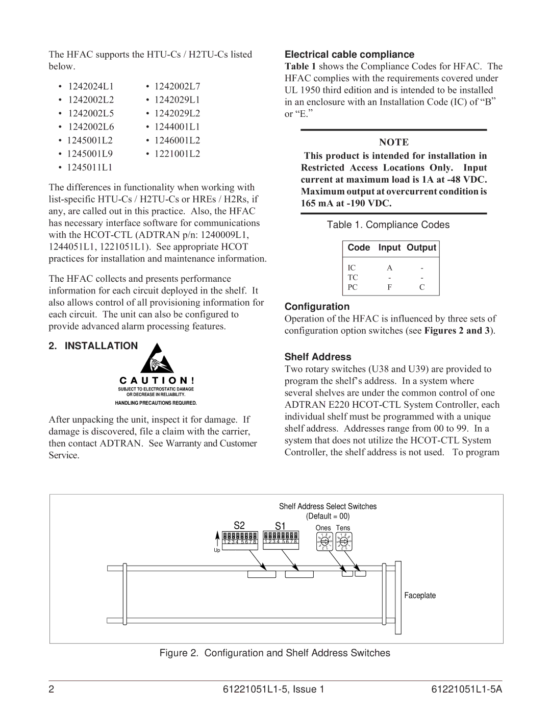
Configuration
Operation of the HFAC is influenced by three sets of configuration option switches (see Figures 2 and 3).
Shelf Address
Two rotary switches (U38 and U39) are provided to program the shelfÕs address. In a system where several shelves are under the common control of one ADTRAN E220
Shelf Address Select Switches
(Default = 00)
S2 S1
1 2 3 4 5 6 7 8 | 1 2 3 4 5 6 7 8 |
Up
Ones
7 | 8 |
9 | |
6 | 0 |
5 | |
4 | 1 |
3 | 2 |
Tens
7 | 8 |
9 | |
6 | 0 |
5 | |
4 | 1 |
3 | 2 |
Faceplate
Figure 2. Configuration and Shelf Address Switches
2 |
|
|