| VIS NO | |
| VIS C | |
Critical | VIS NC | |
AUD NO | ||
| ||
| AUD C | |
| AUD NC | |
| VIS NO | |
| VIS C | |
Major | VIS NC | |
AUD NO | ||
| ||
| AUD C | |
| AUD NC | |
| VIS NO | |
| VIS C | |
Minor | VIS NC | |
AUD NO | ||
| ||
| AUD C | |
| AUD NC |
Fault T
Locate R
261
272
283
294
305
316
327
338
349
3510
3611
3712
3813
3914
4015
4116
4217
4318
4419
4520
4621
4722
4823
4924
5025
HFAC SLOT
(JP1)
Remote
ACO
Table 5. External
(arrow indicates default setting)
| Options Screen |
|
|
|
| Menu Item No. | Function | Description | |
|
|
|
|
|
| 5 | EXT | Alarms Disables and | |
| Disabled |
| enables the alarms | |
|
| resulting from external | ||
| Enabled |
| ||
|
| |||
|
|
| ||
|
|
|
|
|
HTU-C Fuse Alarm
An alarm may be generated as a result of an
3. CONNECTIONS
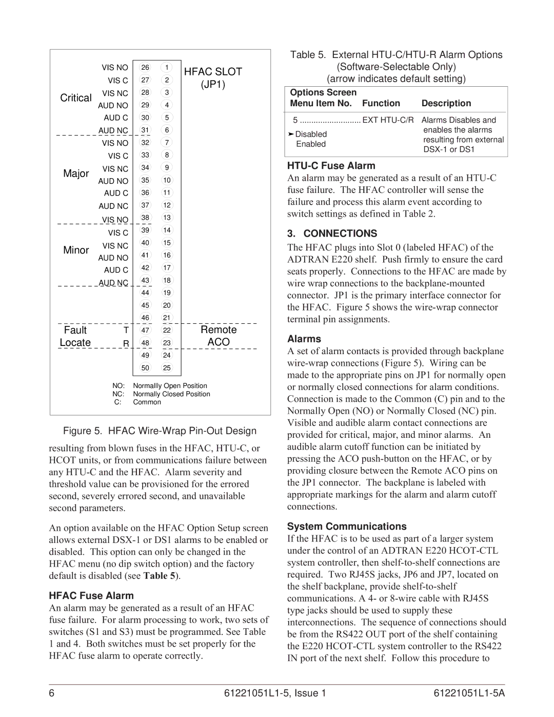
The HFAC plugs into Slot 0 (labeled HFAC) of the ADTRAN E220 shelf. Push firmly to ensure the card seats properly. Connections to the HFAC are made by wire wrap connections to the
Alarms
A set of alarm contacts is provided through backplane
NO: Normallly Open Position
NC: Normally Closed Position
C:Common
Figure 5. HFAC Wire-Wrap Pin-Out Design
resulting from blown fuses in the HFAC,
An option available on the HFAC Option Setup screen allows external
HFAC Fuse Alarm
An alarm may be generated as a result of an HFAC fuse failure. For alarm processing to work, two sets of switches (S1 and S3) must be programmed. See Table 1 and 4. Both switches must be set properly for the HFAC fuse alarm to operate correctly.
or normally closed connections for alarm conditions. Connection is made to the Common (C) pin and to the Normally Open (NO) or Normally Closed (NC) pin. Visible and audible alarm contact connections are provided for critical, major, and minor alarms. An audible alarm cutoff function can be initiated by pressing the ACO
System Communications
If the HFAC is to be used as part of a larger system under the control of an ADTRAN E220
6 |
|