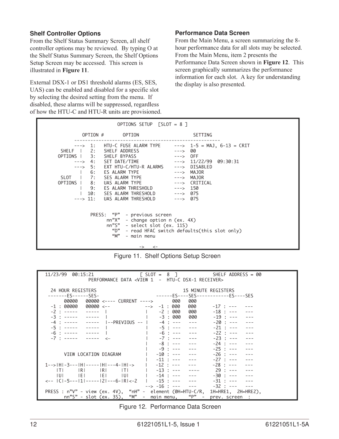
Shelf Controller Options
From the Shelf Status Summary Screen, all shelf controller options may be reviewed. By typing O at the Shelf Status Summary Screen, the Shelf Options Setup Screen may be accessed. This screen is illustrated in Figure 11.
External
Performance Data Screen
From the Main Menu, a screen summarizing the 8- hour performance data for all slots may be selected. From the Main Menu, item 2 presents the Performance Data Screen shown in Figure 12. This screen graphically summarizes the performance information for each slot. A key for understanding the display is also presented.
|
|
| OPTIONS SETUP [SLOT | = 8 ] |
|
| OPTION # | OPTION |
| SETTING | |
| |||||
| 1: | ||||
SHELF | 2: | SHELF ADDRESS | 00 | ||
OPTIONS | 3: | SHELF BYPASS | OFF | ||
| 4: | SET DATE/TIME | 11/22/99 09:30:31 | ||
| 5: | EXT | DISABLED | ||
| 6: | ES ALARM TYPE | MAJOR | ||
SLOT | 7: | SES ALARM TYPE | MAJOR | ||
OPTIONS | 8: | UAS ALARM TYPE | CRITICAL | ||
| 9: | ES ALARM THRESHOLD | 150 | ||
| 10: | SES ALARM THRESHOLD | 075 | ||
| UAS ALARM THRESHOLD | 075 | |||
|
|
| PRESS: | “P” | - previous screen |
|
|
|
|
| |||||
|
|
|
| nn”X” | - change option n (ex. 4X) |
|
|
| |||||||
|
|
|
| nn”S” | - select slot (ex. 11S) |
|
|
| |||||||
|
|
|
|
| “D” - read HFAC switch defaults(this slot only) |
|
| ||||||||
|
|
|
|
| “M” | - main menu |
|
|
|
|
|
|
| ||
|
|
|
|
|
| <- |
|
|
|
|
|
| |||
|
|
|
|
| Figure 11. Shelf Options Setup Screen |
|
| ||||||||
|
|
|
|
|
|
|
|
|
|
|
| ||||
| 11/23/99 00:15:21 |
|
|
| [ SLOT | = | 8 | ] |
| SHELF ADDRESS = 00 |
| ||||
|
|
| PERFORMANCE DATA <VIEW 1 | - |
|
| |||||||||
|
| 24 HOUR REGISTERS |
|
|
|
|
|
|
|
| 15 MINUTE REGISTERS |
|
| ||
|
| SES- |
|
|
|
|
| SES |
| ||||||
|
| 00000 | 00000 | CURRENT | > |
|
| 000 | 000 |
|
|
| |||
|
| 00000 |
|
| 000 |
| |||||||||
|
|
|
|
| : | 000 | 000 |
| |||||||
|
|
|
|
| 000 |
| |||||||||
|
| PREVIOUS |
|
| |||||||||||
|
|
|
|
|
| ||||||||||
|
|
|
|
|
| ||||||||||
|
| <— |
|
|
|
| |||||||||
|
|
|
|
|
|
|
| : |
| ||||||
|
|
|
|
|
|
|
| : |
| ||||||
|
| VIEW | LOCATION DIAGRAM |
|
| : |
| ||||||||
|
|
|
|
|
|
|
| : |
| ||||||
| 1 |
| |||||||||||||
|
| T | R | R | T |
| : | 29 : |
| ||||||
|
| U | E | E | U |
| : |
| |||||||
| < |
| : |
| |||||||||||
|
|
|
|
|
|
| : |
| |||||||
| PRESS : n”V” - view (ex. 4V), | “nH” | - | element | 1H=HRE1, 2H=HRE2), |
| |||||||||
|
| nn”S” - slot (ex. 3S), | “M” | - | main menu, | “P” - | prev. screen | : |
| ||||||
Figure 12. Performance Data Screen
12 |
|
|