System slot ID=AD31 ID=AD30 ID=AD29 ID=AD28 ID=AD27
1 2 3 4 5 6![]()
![]()
![]()
![]()
![]()
![]()
CN1 | CN8 |
| CN6 |
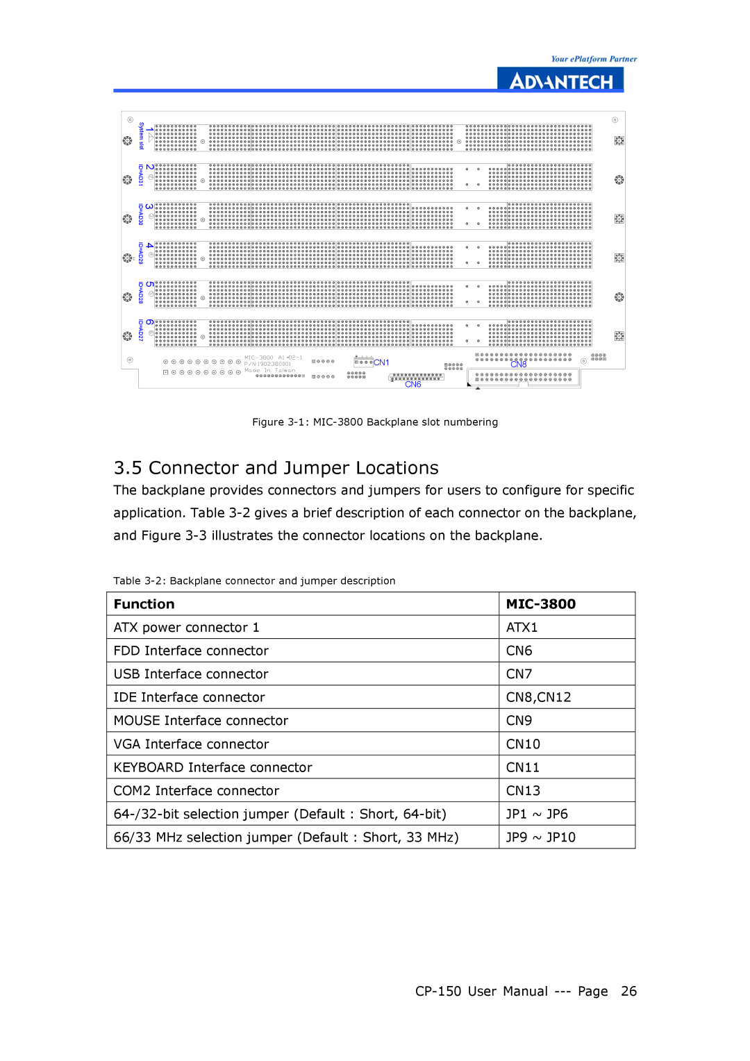
Figure 3-1: MIC-3800 Backplane slot numbering
3.5 Connector and Jumper Locations
The backplane provides connectors and jumpers for users to configure for specific application. Table
Table
Function |
|
ATX power connector 1 | ATX1 |
FDD Interface connector | CN6 |
USB Interface connector | CN7 |
IDE Interface connector | CN8,CN12 |
MOUSE Interface connector | CN9 |
VGA Interface connector | CN10 |
KEYBOARD Interface connector | CN11 |
COM2 Interface connector | CN13 |
JP1 ~ JP6 | |
66/33 MHz selection jumper (Default : Short, 33 MHz) | JP9 ~ JP10 |