ATX1 ![]()
![]()
![]()
![]() CN9
CN9
CN10 | CN13 | CN12 |
CN11 | CN7 | |
CN2 | ||
|
![]() JP1
JP1
![]()
![]() JP2
JP2
![]()
![]() JP3
JP3
![]()
![]() JP4
JP4
![]()
![]() JP5
JP5
JP9![]()
![]() JP10
JP10 ![]() JP6
JP6
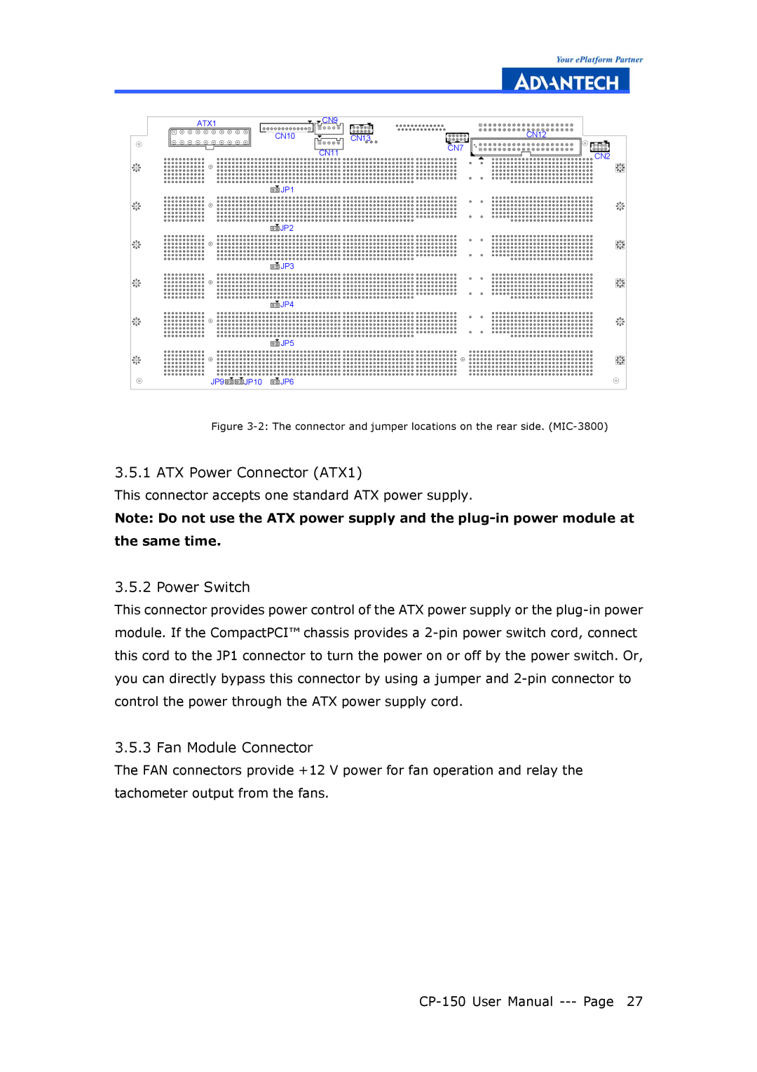
Figure 3-2: The connector and jumper locations on the rear side. (MIC-3800)
3.5.1 ATX Power Connector (ATX1)
This connector accepts one standard ATX power supply.
Note: Do not use the ATX power supply and the
3.5.2 Power Switch
This connector provides power control of the ATX power supply or the
3.5.3 Fan Module Connector
The FAN connectors provide +12 V power for fan operation and relay the tachometer output from the fans.