the peripheral slots have logical numbers 2~5. The connectors in logical slot 1 are designated as
Nomenclature for connectors in the other slots is similar, such as
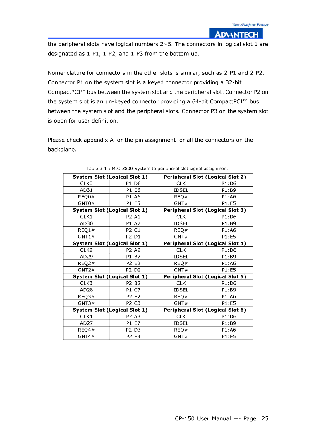
Please check appendix A for the pin assignment for all the connectors on the backplane.
Table
System Slot (Logical Slot 1) | Peripheral Slot (Logical Slot 2) | ||
CLK0 | P1:D6 | CLK | P1:D6 |
AD31 | P1:E6 | IDSEL | P1:B9 |
REQ0# | P1:A6 | REQ# | P1:A6 |
GNT0# | P1:E5 | GNT# | P1:E5 |
System Slot (Logical Slot 1) | Peripheral Slot (Logical Slot 3) | ||
CLK1 | P2:A1 | CLK | P1:D6 |
AD30 | P1:A7 | IDSEL | P1:B9 |
REQ1# | P2:C1 | REQ# | P1:A6 |
GNT1# | P2:D1 | GNT# | P1:E5 |
System Slot (Logical Slot 1) | Peripheral Slot (Logical Slot 4) | ||
CLK2 | P2:A2 | CLK | P1:D6 |
AD29 | P1:B7 | IDSEL | P1:B9 |
REQ2# | P2:E2 | REQ# | P1:A6 |
GNT2# | P2:D2 | GNT# | P1:E5 |
System Slot (Logical Slot 1) | Peripheral Slot (Logical Slot 5) | ||
CLK3 | P2:B2 | CLK | P1:D6 |
AD28 | P1:C7 | IDSEL | P1:B9 |
REQ3# | P2:E2 | REQ# | P1:A6 |
GNT3# | P2:C3 | GNT# | P1:E5 |
System Slot (Logical Slot 1) | Peripheral Slot (Logical Slot 6) | ||
CLK4 | P2:A3 | CLK | P1:D6 |
AD27 | P1:E7 | IDSEL | P1:B9 |
REQ4# | P2:D3 | REQ# | P1:A6 |
GNT4# | P2:E3 | GNT# | P1:E5 |