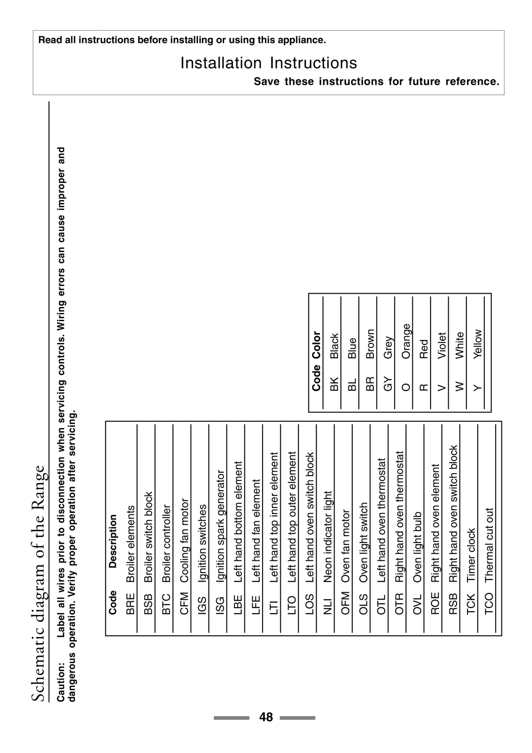
U104001-03 specifications
The Aga Ranges U104001-03 is a remarkable embodiment of luxurious cooking technology, combining classic aesthetics with modern functionality. Crafted for both culinary enthusiasts and professional chefs, this range is built to elevate the cooking experience in any kitchen setting.One of the standout features of the U104001-03 is its unique heat retention and distribution system. The range utilizes cast iron cooking technology, which not only retains heat exceptionally well but also distributes it evenly across all cooking surfaces. This ensures consistent cooking results, crucial for baking and roasting. The gentle, even heat allows for the development of complex flavors, making it ideal for creating gourmet dishes.
The U104001-03 offers multiple cooking options with its wide array of burners and ovens. It typically includes several gas burners, providing chefs with precise temperature control for various cooking styles. From simmering delicate sauces to achieving high-heat searing, these burners adapt effortlessly to different culinary techniques.
Another defining characteristic of the Aga range is its iconic design. The U104001-03 boasts a robust, traditional aesthetic that can serve as a stunning centerpiece in any kitchen. Available in an array of vibrant colors, this range allows homeowners to customize its appearance to match their unique style and decor. The enamel finish not only enhances its visual appeal but also makes for easy cleaning and maintenance.
In terms of technology, the Aga Ranges U104001-03 incorporates modern conveniences, such as programmable timers and dual-fuel options, allowing users to seamlessly switch between gas and electric cooking. The electronic ignition system ensures quick and safe lighting of the burners, enhancing user experience.
Safety is also a priority in the design of this range. Features like flame failure devices and automatic shut-off mechanisms provide peace of mind while cooking, making it suitable for families who prioritize safety in the kitchen.
The U104001-03 is engineered for durability, built with high-quality materials that withstand the rigors of daily cooking. Its robust construction ensures longevity, making it a worthwhile investment for cooking aficionados.
In summary, the Aga Ranges U104001-03 is a blend of tradition and innovation, delivering exceptional cooking performance along with stunning aesthetics. Its advanced features and thoughtful engineering make it a centerpiece for any serious cook, providing an unparalleled culinary experience. Whether you're roasting, baking, or simmering, this range is designed to inspire and elevate every meal.

