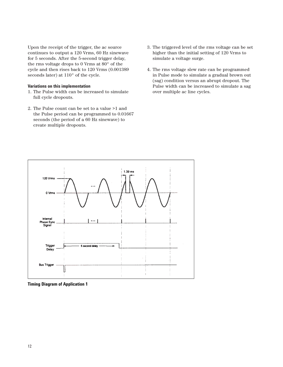
Upon the receipt of the trigger, the ac source continues to output a 120 Vrms, 60 Hz sinewave for 5 seconds. After the
Variations on this implementation
1.The Pulse width can be increased to simulate full cycle dropouts.
2.The Pulse count can be set to a value >1 and the Pulse period can be programmed to 0.01667 seconds (the period of a 60 Hz sinewave) to create multiple dropouts.
3.The triggered level of the rms voltage can be set higher than the initial setting of 120 Vrms to simulate a voltage surge.
4.The rms voltage slew rate can be programmed in Pulse mode to simulate a gradual brown out (sag) condition versus an abrupt dropout. The Pulse width can be increased to simulate a sag over multiple ac line cycles.
Timing Diagram of Application 1
12