Agilent 6800 series setup (continued)
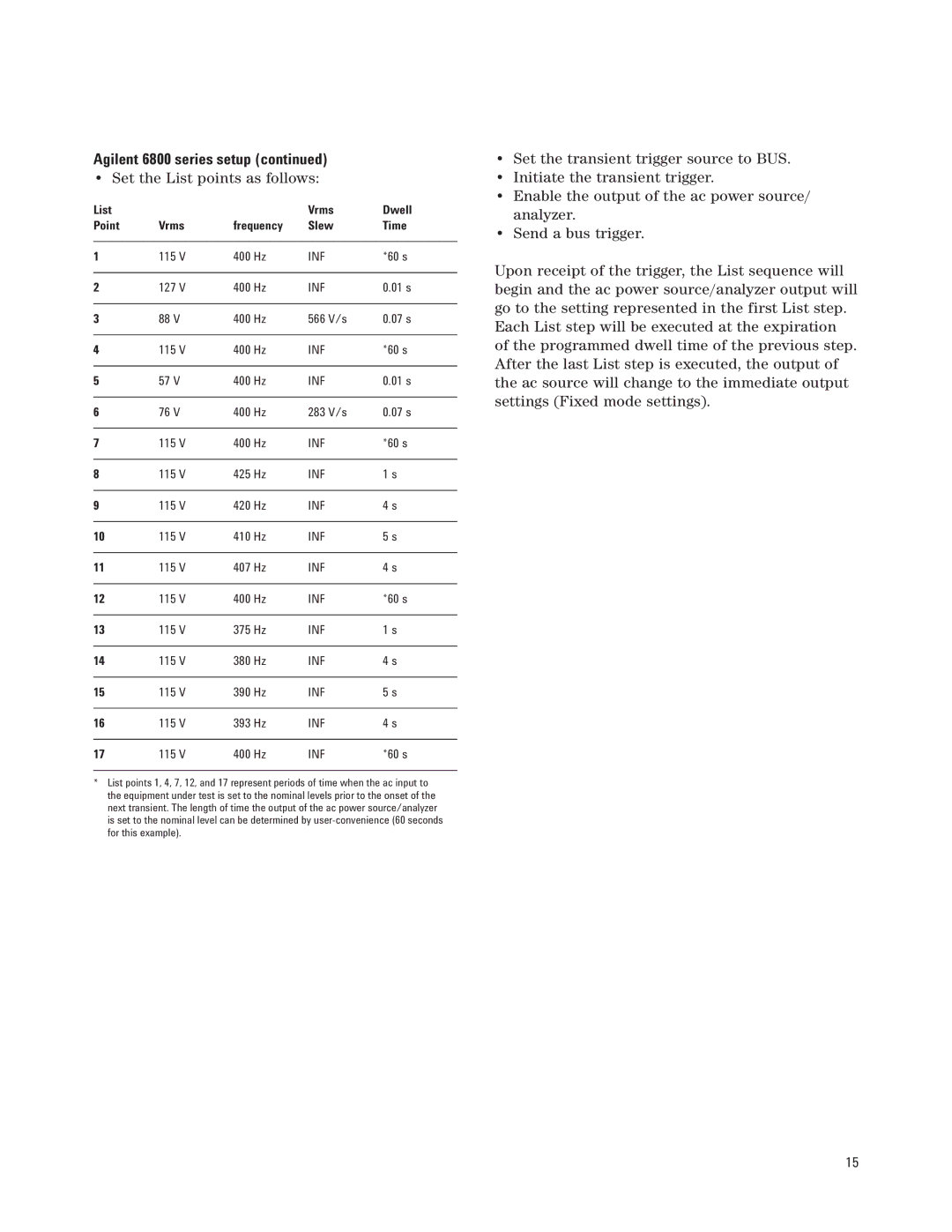
• Set the List points as follows:
List |
|
| Vrms | Dwell |
Point | Vrms | frequency | Slew | Time |
|
|
|
|
|
1 | 115 V | 400 Hz | INF | *60 s |
|
|
|
|
|
2 | 127 V | 400 Hz | INF | 0.01 s |
|
|
|
|
|
3 | 88 V | 400 Hz | 566 V/s | 0.07 s |
|
|
|
|
|
4 | 115 V | 400 Hz | INF | *60 s |
|
|
|
|
|
5 | 57 V | 400 Hz | INF | 0.01 s |
|
|
|
|
|
6 | 76 V | 400 Hz | 283 V/s | 0.07 s |
|
|
|
|
|
7 | 115 V | 400 Hz | INF | *60 s |
|
|
|
|
|
8 | 115 V | 425 Hz | INF | 1 s |
|
|
|
|
|
9 | 115 V | 420 Hz | INF | 4 s |
|
|
|
|
|
10 | 115 V | 410 Hz | INF | 5 s |
|
|
|
|
|
11 | 115 V | 407 Hz | INF | 4 s |
|
|
|
|
|
12 | 115 V | 400 Hz | INF | *60 s |
|
|
|
|
|
13 | 115 V | 375 Hz | INF | 1 s |
|
|
|
|
|
14 | 115 V | 380 Hz | INF | 4 s |
|
|
|
|
|
15 | 115 V | 390 Hz | INF | 5 s |
|
|
|
|
|
16 | 115 V | 393 Hz | INF | 4 s |
|
|
|
|
|
17 | 115 V | 400 Hz | INF | *60 s |
*List points 1, 4, 7, 12, and 17 represent periods of time when the ac input to the equipment under test is set to the nominal levels prior to the onset of the next transient. The length of time the output of the ac power source/analyzer is set to the nominal level can be determined by
•Set the transient trigger source to BUS.
•Initiate the transient trigger.
•Enable the output of the ac power source/ analyzer.
•Send a bus trigger.
Upon receipt of the trigger, the List sequence will begin and the ac power source/analyzer output will go to the setting represented in the first List step. Each List step will be executed at the expiration of the programmed dwell time of the previous step. After the last List step is executed, the output of the ac source will change to the immediate output settings (Fixed mode settings).
15